I bought this and a few others from an electronics tech who says they are not repairable. When it is turned on, main power realy clicks, a second relay turns on and another relay engages for a couple of millisecons and it displays overload on the front panel.
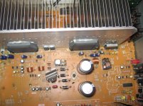
The electronics technician snipped all of the leads on the output chips. I inserted a piece of paper between contacts of the relays to eliminate the circuit they are feeding. The two big capacitors are slightly bulged from what I can tell. I do not have shematics. This receiver is worth nothing more that educational material and I would really like to solve this mystery.
The electronics technician snipped all of the leads on the output chips. I inserted a piece of paper between contacts of the relays to eliminate the circuit they are feeding. The two big capacitors are slightly bulged from what I can tell. I do not have shematics. This receiver is worth nothing more that educational material and I would really like to solve this mystery.
Attachments
Cut them to remove them from the circuit. To eliminate them from being the cause of overload. I read a few articles about these being replaced and problem persisting. Please help me to understand. If they are removed from the circuit, how can they still be the cause of the overload?
.... If they are removed from the circuit, how can they still be the cause of the overload?
They can't, however the protection circuitry may need to see a zero volt condition on the output line.
Try applying a short circuit (to the zero volt line) from the speaker output line. You would have to do this BEFORE the relay of course.
I bought this and a few others from an electronics tech who says they are not repairable. When it is turned on, main power realy clicks, a second relay turns on and another relay engages for a couple of millisecons and it displays overload on the front panel.
The electronics technician snipped all of the leads on the output chips. I inserted a piece of paper between contacts of the relays to eliminate the circuit they are feeding. The two big capacitors are slightly bulged from what I can tell. I do not have shematics. This receiver is worth nothing more that educational material and I would really like to solve this mystery.
I have a Technics SA-160 receiver that is constructed like that with a power hybrid flanked by power supply regulators. After years of being moved around the solder joints on those regulators failed and only parts of the unit would come on. Removing all the old solder and replacing with new brought it back to working great.
The tech that says they are not repairable isn't very ambitious or adventurous. It's a lot different form other manufacturers of the same vintage but certainly doable. I've had it open 3 times, first to change all the coupling caps and increase the value by 3 (low end roll off I didn't like), replace the AN6552 opamps with OPA2134s and re-tune the 5 band graphic equalizer moving the 320 Hz to 180 Hz and the 80 Hz to 25 Hz. The second time a couple years later was to resolder the power devices and bring it back to life. The third time was in December to convert a record output to a preamp out so I can use the Koss ESP-950s with it.
I don't remember where I bought the schematic but it was a .PDF somebody scanned and charged me $10 for. BTW I only paid about $25 for the receiver on eBay.
G²
- Status
- This old topic is closed. If you want to reopen this topic, contact a moderator using the "Report Post" button.