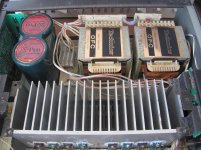
Someone gave me this amplifier for parts because one channel was not working and the shop he took it to repair told him that this amp was beyond repair with to many parts broken. i opened it and all 4 output transistors are shorted, one driver shorted, 2 resistors opened, and a small electrolytic exploded, so now i dont know what to do...i can try to repair it to myself or took all the good parts i can use later to make something usefull for me. This amp looks too complicated for me to try to repair it, because i know that i can replace the parts that are broken, turn it on, and boommmm, and discover that more parts needed to be replaced. Now my question is: Does this amp deserve an attempt to be repaired for his quality or just turn it to parts ?
Thanks
Thanks
Attachments
It is a very nice amplifier and will not be too complicated to repair if you have and can read the service manual.
Yes, i downloaded the service manual and if you say it is a nice amplifier, then i will have a go at it, i will try to repair it.
I found a small 1uf/100V exploded in the -60 V supply, maybe thats what caused all this? maybe shorted for moments the negative supply rail and caused all this ?
Thanks for your reply !
I found a small 1uf/100V exploded in the -60 V supply, maybe thats what caused all this? maybe shorted for moments the negative supply rail and caused all this ?
Thanks for your reply !
Well, the chassis is not that beautifull, but first i will try to repair it,only the right channel is not working,but it is a complicated amplifier for me to repair ( i am not a specialist),then if i not suceed in the repair maybe i follow your sugestion. I have to check all the transistors and resistors in the Rch to see what more is damaged.
Best regards
Best regards
This is an amplifier I would hang on to if at all possible. They are about as low-noise as consumer amps get, thanks to a 2-stage volume control. I do realize the power amp is a bit intimidating with the bootstrapped opamp supplies and all.
The exploded 100V electrolytic may indicate that the respective rail went much higher than it should have, possibly due to the other one being shorted out to ground by a dead output transistor. Work your way backwards from the output in the damaged channel and thoroughly check all parts.
Not sure whether you can still get authentic 2SC3944A/2SA1535A. It would definitely be a good idea to look for current replacements of the Toshiba output devices, since few things are faked as often as Toshiba power transistors.
Someone gave me this amplifier for parts because one channel was not working and the shop he took it to repair told him that this amp was beyond repair with to many parts broken. i opened it and all 4 output transistors are shorted, one driver shorted, 2 resistors opened, and a small electrolytic exploded, so now i dont know what to do...i can try to repair it to myself or took all the good parts i can use later to make something usefull for me. This amp looks too complicated for me to try to repair it, because i know that i can replace the parts that are broken, turn it on, and boommmm, and discover that more parts needed to be replaced. Now my question is: Does this amp deserve an attempt to be repaired for his quality or just turn it to parts ?
Thanks
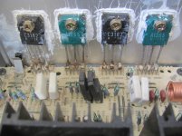
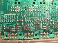
Looking at the second image there is white heat transfer compound smeared over the heat sinks - equipment would never pass a factory quality control inspection in that state. I would expect the original compound would have been transparent anyway.
If there were previous repairs by parties unknown, a repair man might not want to spend a lot of time on the job and risk a come-back due to another's work.
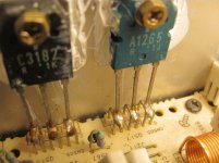
Apart from the white compound I notice brown stains on the power transistor leads and the solder is has a dull appearance where it should be shiny.Part of the tops are blown off the transistors in the foreground. It appears there has been a long standing over-heating problem leading to the ultimate failure.
Such a state might have come about through the incorrect adjustment of the current flowing through the output transistors under no signal conditions (Iq or quiescent current). Sometimes people think they can fine tune equipment - cars, amplifiers, etc and improve the performance.
With a little knowledge they might know that Class A amplifiers run hot, and seeing this Class AA unit is not conforming to that belief, and made an adjustment. The equipment does have a small Class A element to it but it is low power and separate from the power stage which runs in Class AB.
If so, the damage may be limited - fingers crossed just the power output and driver stages.
For setting up when you have replaced the faulty parts I suggest isolating the collector leads for the output stage so you can interpose a wire wound resistor between these and the supply rails ( look for supply rail fuses you can remove and clip a resistor across). 220 ohms at 10 watts should be enough to limit the current flow to avoid the risk of damage. You can measure the voltage drop across these and deduce the current flow - this being the voltage divided by 220.
The results should be identical for either resistor and the voltage level in the millivolt range of your meter and adjustable - downwards quickly if the wire-wound resistors can burn fingers.
A quick dab with a moistened finger will tell you all you need to know. You would try that before measuring in case you need to de-power and continue the fault finding process.
If all is well reduce the voltage drop across the wire-wound resistors as low as possible, remove the resistors and solder the joints. You can then follow the Service Manual procedure for setting the no signal output current and checking the d.c. level at the positive speaker output terminal.
This amplifier is high power with 120 volts across the rails - enough to give a nasty shock, so there is a need to be careful not to touch parts connected to the positive and negative supply rails at the same time.
Last edited:
This is an amplifier I would hang on to if at all possible. They are about as low-noise as consumer amps get, thanks to a 2-stage volume control. I do realize the power amp is a bit intimidating with the bootstrapped opamp supplies and all.
The exploded 100V electrolytic may indicate that the respective rail went much higher than it should have, possibly due to the other one being shorted out to ground by a dead output transistor. Work your way backwards from the output in the damaged channel and thoroughly check all parts.
Not sure whether you can still get authentic 2SC3944A/2SA1535A. It would definitely be a good idea to look for current replacements of the Toshiba output devices, since few things are faked as often as Toshiba power transistors.
I was having a better look tonight to the amp, and i found some more shorted transistors and opened resistors,and a strange thing is that almost all the shorted transistors i found are PNP types connected to the negative supply voltage (-60 V),so definitly something happened with this negative supply. I still can get some original 2SA1535A to replace, but the output ones i was wondering if i can replace them by the A1302/C3281 because i have some original toshiba in stock.
Best regards
Looking at the second image there is white heat transfer compound smeared over the heat sinks - equipment would never pass a factory quality control inspection in that state. I would expect the original compound would have been transparent anyway.
If there were previous repairs by parties unknown, a repair man might not want to spend a lot of time on the job and risk a come-back due to another's work.
Apart from the white compound I notice brown stains on the power transistor leads and the solder is has a dull appearance where it should be shiny.Part of the tops are blown off the transistors in the foreground. It appears there has been a long standing over-heating problem leading to the ultimate failure.
Such a state might have come about through the incorrect adjustment of the current flowing through the output transistors under no signal conditions (Iq or quiescent current). Sometimes people think they can fine tune equipment - cars, amplifiers, etc and improve the performance.
With a little knowledge they might know that Class A amplifiers run hot, and seeing this Class AA unit is not conforming to that belief, and made an adjustment. The equipment does have a small Class A element to it but it is low power and separate from the power stage which runs in Class AB.
If so, the damage may be limited - fingers crossed just the power output and driver stages.
For setting up when you have replaced the faulty parts I suggest isolating the collector leads for the output stage so you can interpose a wire wound resistor between these and the supply rails ( look for supply rail fuses you can remove and clip a resistor across). 220 ohms at 10 watts should be enough to limit the current flow to avoid the risk of damage. You can measure the voltage drop across these and deduce the current flow - this being the voltage divided by 220.
The results should be identical for either resistor and the voltage level in the millivolt range of your meter and adjustable - downwards quickly if the wire-wound resistors can burn fingers.
A quick dab with a moistened finger will tell you all you need to know. You would try that before measuring in case you need to de-power and continue the fault finding process.
If all is well reduce the voltage drop across the wire-wound resistors as low as possible, remove the resistors and solder the joints. You can then follow the Service Manual procedure for setting the no signal output current and checking the d.c. level at the positive speaker output terminal.
This amplifier is high power with 120 volts across the rails - enough to give a nasty shock, so there is a need to be careful not to touch parts connected to the positive and negative supply rails at the same time.
I think the output transistors are the original ones, i can see that nothing was replaced in this print, as can be seen in this photos, but i agree that there is an exess of compound in the output transistors.
Attachments
If all is well reduce the voltage drop across the wire-wound resistors as low as possible, remove the resistors and solder the joints.
I should have said remove the resistors, replace the fuses and if the connection between the output stage collector transistors has been broken elsewhere restore the connection - by soldering if necessary.
This repair is going to be slow for me, today i removed the all main board because it is easier to me to check everything and i did not find more parts broken, so i will start to replace what i have available at the moment, order the other parts, put everything together, and see what happens...i will put small watt resistors in the supply to the board to make sure it does not blow again.
Attachments
This repair is going to be slow for me, today i removed the all main board because it is easier to me to check everything and i did not find more parts broken, so i will start to replace what i have available at the moment, order the other parts, put everything together, and see what happens...i will put small watt resistors in the supply to the board to make sure it does not blow again.
A very wise approach.
When you say small watt resistors in the supply to the board I take it small relates to the size and power rating and not the resistance value.
You need the resistance to limit the current - there is a lot of energy in capacitors charged to 60 volts - This is measured in Joules calculated as half the product of the capacitance in Farads and the square of the voltage - accordingly there is 4 times as much energy in the capacitor than there would be at 30 volts.
If there is still a residual fault a low value resistor is not going to do much to hold back that momentum in the time it takes to burn out.
From the image of the board I could not see any fuse holders where you could bridge the gap with a resistor as described, however there are a number of wire links on the component side - these can help with servicing as the continuity can be broken and restored without accessing the copper side of the board.
The ones of interest will be those feeding the collector leads of the output and driver transistors. These you would cut at an angle of 45 degrees which will help mating the ends and solder flow when you need to rejoin the two halves. You can solder test resistors to the separated link ends.
Having looked up the Service Manual I note the current drawn by the output stages is set by VR403 which for set up purposes is set to minimum conduction by turning fully counterclockwise.
As a guess the power and driver stage might draw 100 - 200 milliamps when set up correctly. It should be much less than that with VR403 turned down but I took the first more conservative approach in my calculations.
The value of set up resistor was 220R wire-wound 10 watts. The wattage is determined from W (watts) = I (amps)squared by R (resistance in Ohms) - so we have (.2)^2 by 220 which equals 8.8 watts.
If there is a fault the 10 watt wire-wound resistor is going to get hot fairly quickly, so you would have one hand on the off switch and a moistened finger on the body of the wire-wound resistor.
If you replace the 10 watt resistor with a 1 watt carbon film of the same value that will get hot when conducting 60 or so milliamps and smoke out if much beyond that. Under fault conditions that will happen very quickly and you will have less time to react - breathing toxic fumes and burning a finger, are risks to avoid.
Thank you mjona for your comments and interest. I will follow your sugestion and put 220 ohm resistors feeding the output transistors to avoid more damage if something goes wrong. Today i put some components in the board, and ordered the outputs (2SA1265/2SC3182) wich will take about 2 days to be in my hands. I also took out the front end board to inspect, and seems to be everything ok .
Best regards
Good luck, I hope it all works out for you.
- Status
- Not open for further replies.
- Home
- Amplifiers
- Solid State
- Technics SU-VX800 Given to me