Hi all,
After restoring a Scott A426 thanks to some of you I found two other amps from my fathers collection down in the basement, a Technics su v85a and a Pioneer sa7800. I will keep the pioneer for later and don't know if it works or not but the Technics got my interest. I've read that it was designed for the army and that there aren't that much of them around.
I fired it up and everything seemed normal, lights came on, relay clicked but I decided to wait for it to warm up before testing. I just checked the dc offset which was at 5mV on one and 3 on the other channel. After 20 minutes 3 transistors and one resistor blew. I replaced those and started checking because the light bulb I placed in series lit up. I found different resistors and some diodes that were open or shorted so I replaced them too but now I'm stuck, the lights stay out whereas the bulb lights and no relay. The voltages at the power supply when power amp is disconnected are ok.
I could use some help troubleshooting 🙂
There is poorly scanned manual for this model at Electrotanya but you should always refer to a schematic others can also see when you describe the problems you find.
The SU-V series class AA amplifiers are variants of the original Sandman "S class", SEA series amplifiers. These were not regular class AB amplifiers but operated along the lines of current dumping designs like most Quad designs but Technics did dumb the designs down along more conventional design principles over the period the series was in production. Note that the amplifier fires up a tiny "voltage control amplifier" first which is allowed to stabilize before connecting in bridge with a much larger "current drive" amplifier which provides the muscle to drive speakers, in the next step of powering up.
The topology is not easy to follow as much of the control system is contained in the special ICs and this makes them unusual and hard for DIYs and even service people to understand. The next problem is that some of these ICs can be virtually unobtanium but Panasonic AN7062 at least is available (if genuine). The protection chip AN7073, may not be so easy to find and both of these are critical to routine, safe operation. Other ICs appear to be conventional opamps and digital logic chips but these will probably be ok.
I don't wish to be negative about this repair, but it won't be easy to get specific guidance or correct parts for this one which I believe you will find necessary.
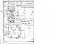
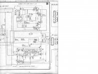
I have a very decent service manual so here are the schematics for the power amp :


Have been replaced by original parts, no equivalents (also all the electrolytic capacitors are new) : Both output transistors on right channel Q506 and Q508, Q516 and Q518, IC502 which was shorted, R504 and R502.
I'm quite new to all this but I have done some research about the amp and have some idea of what you're talking about.
There is one part that I left out before which is that when I replaced the transistors and the opamp mentioned before the "voltage control amp" worked fine, the led on the front lit up, same for the "current drive amp" and the relay even clicked but on the right channel I had no voltage at the test points whatever the position of VR452 and VR502 were (I tested them to be sure that wasn't the problem and they are both working). I had sound with headphones and no dc offset but not having any bias didn't seem safe so I continued searching. I found that D508 was shorted, R460 was open and Q510 was shorted. I replaced the three of them and now I don't have anything, no lights and no relay. As it seemed to be working before replacing those parts is it fair to assume that none of the ICs is bad ? The protection chip is working (there is a test described in the service manual and when the amp was partially working I followed the instruction and the result was good).
I hope this makes things a little easier, I'm really curious to hear this amp work again so I hope there is a way to do this.
Last edited:
Just trying to pour some new life into this thread, I'm still looking for some help with the repair of this Technics amp. Is there someone, with the information I gave in a previous post, that could help me troubleshoot the beast ?
I left this project on the side for a while but I really want to be able to hear what this amp sounds like. I got the multimeter back out and started searching.
I disconnected the two output transistors (Q506 and Q508) from the faulty channel and the amp fires up, the two drive indicators come on and the relay clicks.
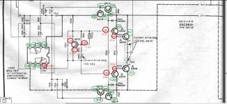
This gave me the time to check all the voltages across the right channel and I narrowed it down to this :

The IC has already been replaced as well as q510, R512 et D508
Any suggestions ?
I disconnected the two output transistors (Q506 and Q508) from the faulty channel and the amp fires up, the two drive indicators come on and the relay clicks.
This gave me the time to check all the voltages across the right channel and I narrowed it down to this :

The IC has already been replaced as well as q510, R512 et D508
Any suggestions ?
Back with some good and some less good news. The amp now fires up fine, both voltage and current driver amp lights come on and relay closes. I went over the whole power amplifier board and all the voltages are where they should be. After setting the two adjustments a quick test and yes, there is sound. So far the good news, bad news is one channel is louder than the other and after idling for about 20 minutes the current drive amp light went off again and relay opened. I immediately turned off the amp and found q516 to be shorted. Fortunately nothing else went bad so I changed Q516 and did the whole process over again. Amp fired up, all the voltages ok but after sitting 20 minutes, q516 died again.
Since IC502 has already been replaced, I'd guess you have an oscillation problem there. This looks to be a "tone control in the feedback" type affair, which can go unstable when said controls go intermittent. Also replace any small electrolytics in the feedback.
So I should be looking in the preamp section ? The whole amp had a full recap already and the problem actually started after this.
I still haven't managed to get any further in my troubleshooting with this amplifier.
I checked the output with an oscilloscope with a 1000Hz signal on the input and I have to perfect and equal sine waves. Still Sometimes the relay closes and sometimes it doesn't. I didn't set the bias for either voltage control or bias amp and so far q518 hasn't failed again.
I checked the output with an oscilloscope with a 1000Hz signal on the input and I have to perfect and equal sine waves. Still Sometimes the relay closes and sometimes it doesn't. I didn't set the bias for either voltage control or bias amp and so far q518 hasn't failed again.
- Status
- Not open for further replies.
- Home
- Amplifiers
- Solid State
- Technics SU V85A