I got my hands on a working old 2 Channel Technics SU-7100. I'm interested to rebuild this and hear a good pair of STK0039 Amplifiers.
1 - Is this worth rebuilding?
2 - My thought was to just replace all of the capacitors and keep all else.
Suggestions are welcome on the thought of what to replace.
Thanks!
PS - sorry if this is the wrong forum for this one.
1 - Is this worth rebuilding?
2 - My thought was to just replace all of the capacitors and keep all else.
Suggestions are welcome on the thought of what to replace.
Thanks!
PS - sorry if this is the wrong forum for this one.
If you like the unit, replacing the electrolytics and tantalums (only) is worthwhile. Shouldn't be too hard.
Pretty much that.
There are little over two dozen electrolytics in the whole unit, so there's not that much to it. The only fun part may be finding suitable replacements for the two 1µ/50 bipolars.
I would also check what sort of voltage drop you are getting across R227/228 and R239/240. 2SA798s are quite notorious for failing and going leaky, and anything indicating more than at most 2 µA of base current would be very suspect (that's about 165 mV over the former or 80 mV over the latter). People have been replacing these with two similar single ECB pinout transistors joined at the emitter and epoxied together, e.g. KSA992.
Excellent advice as always on diyaudio. Appreciate it and now in search of parts.
Get good ones for the output stage supply: higher ripple current, 105C, and extra voltage margin.
Bipolar caps: UES1H010MDM Nichicon | Mouser
Last edited:
I restored a Technics SU-7100 once, with both STK0039 and all other semiconductors still working.
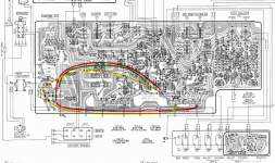
Apart from the recap, I analyzed the PCB layout and ended up correcting some of the original supply tracks. These are meandering across the PCB going from one current sink to another, reaching the sensitive voltage amp stages last. My intention was to give it a proper star design.
red: positive rail
amber: negative rail
green: ground
dotted blue: removed jumper or scratched track
Soundwise, the result of the restoration was very pleasing.
- Johannes
Attachments
Get good ones for the output stage supply: higher ripple current, 105C, and extra voltage margin.
Bipolar caps: UES1H010MDM Nichicon | Mouser
Do you know the positions where the output stage supply caps are?
Presumably C213, 214, 234, maybe C235 as well.Do you know the positions where the output stage supply caps are?
Panasonic FC or FM series caps are about as fancy as you'd need.
Note: C213 should be uprated, it's a 25 V cap on 24.4 V stock. Should be no problem, they have gotten much smaller anyway, so you may find a 50 V or so is the same physical size these days. I would generally recommend a rating of maybe twice the usual voltage applied for these smaller electrolytics. (Part of why they have gotten smaller is much better quality control result in far less spread. Back in the day a "good" 25 V may actually have sustained 50 V, today few will. So I'd rather up the rating a bit.)
It may be a good idea to keep an eye on the various switch contacts in the signal path as well.
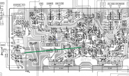
I'm not sure whether this would have a super great effect, the LTP/VAS supply is being RC filtered after all... I would consider doing just the mod pertaining to ground. (EDIT: See attachment. Color scheme basically the same - thin blue = cut, thick green = ground wire.) Making the path from D201 to point (4) lower in impedance may also be worth considering, but honestly it's fairly short as-is.I restored a Technics SU-7100 once, with both STK0039 and all other semiconductors still working.
Apart from the recap, I analyzed the PCB layout and ended up correcting some of the original supply tracks. These are meandering across the PCB going from one current sink to another, reaching the sensitive voltage amp stages last. My intention was to give it a proper star design.
Speaking of ground, where did you cut that? Maybe I'm just blind or you forgot to draw it. I'd suggest next to C231 if you don't want to unsolder anything.
As someone else wrote here recently, these Technics amps were quite well engineered and usually don't have anything major wrong with them as far as execution goes. Of course you would no longer use 250k volume pots and such these days, but that's just how things were back then.
Attachments
Last edited:
Rerouting supply paths: Going for star topology at the very least makes sense for the high-current rails to the STKs. Originally both, positive and negative rail, first visit STK IC201 and then continue from there to STK IC202.
Recommended extra ground connection:
You are right about the missing cut. I believe I put it close to where you have marked it.
Your recommendation for adding another ground connection (D201 to Cinch ground) makes sense as well, as I now see.
Recommended extra ground connection:
You are right about the missing cut. I believe I put it close to where you have marked it.
Your recommendation for adding another ground connection (D201 to Cinch ground) makes sense as well, as I now see.
I see what you mean. It probably isn't terribly terribad as they generally managed to keep the V+/V- tracks next to each other for low inductance. (Really not a bad layout for the time.) Still not as good as two twisted wires of adequate diameter, mind you.Rerouting supply paths: Going for star topology at the very least makes sense for the high-current rails to the STKs. Originally both, positive and negative rail, first visit STK IC201 and then continue from there to STK IC202.
That part comprises the lower two supply wires, the removed jumper next to IC201 and the cut next to IC202's heatsink.
The other two wires and cuts can be left out, they really aren't doing very much as I said.
- Home
- Amplifiers
- Solid State
- Technics SU-7100 Rebuild