I'm having some issues with a Technics ST-S707 tuner that I recently picked up.
I'm hoping someone with more expertise than myself (nil) with tuners can help me out with this. The tuner pulls in a signal pretty well but as the audio level goes up, the signal seems to cut out.
It is NOT my receiver/amplifier because it is happening at the tuner. In fact I don't even have to have the tuner hooked up to anything to observe it.
I can observe it on the tuner display with the Quartz lock, FM IF and signal center display actually pulsing off and on in concert with the audio level being received.
What I mean is, if, say the DJ shouts suddenly, it cuts out momentarily with the associated pulsing off/on of the previously mentioned display parameters. It's like the signal level is overloading something causing it to cut out - but the signal strength, while strong, is certainly not THAT strong.
Any ideas where to start looking. I checked all the electrolytic capacitors (changed a few suspect ones), but that had no effect on the issue.
Does it just need a tuner alignment or are there some sick parts to go after?
TIA
Well, it doesn't happen on AM although the signal was so bad it took a while to determine it is an FM only issue. I did take another look at the signal strength and the signal strength seems to be dropping enough that it comes out of "lock" but it definitely happens in conjunction with the "level" as I mentioned previously.
Well, it doesn't happen on AM although the signal was so bad it took a while to determine it is an FM only issue
.
This is encouraging.
Now as this tuner is well equipped with capabilities, use the reduction method to do the initial FM troubleshooting without poking inside.
Ensure the FM antenna is properly connected.
Dial on a strong signal.
25 kHz/100 kHz tuning selector to 25kHz.
Auto/ Manual selector to Manual.
Muting to OFF
Mono/ Stereo to Mono
RF narrow
IF narrow
If the problem is due to some switch settings, the above combination is the least interfering.
If with these settings you have no signal cut-out problem, change switches position –one at a time-starting with the switches at the bottom of the list.
Keep notes on a paper of the results for each switch position.
If you want to, report back.
George
Most FM tuners have an off-tune mute facility. This usually uses signal strength, but some also use the degree of off-tuning. Obviously they need to remove the audio before using the discriminator output to detect off-tuning, and there will be some sort of low pass filter to do this. My guess is that an electrolytic has dried up or gone open circuit, so the muting circuit is now seeing the audio instead of just a DC level.
Try to identify the FM IF and discriminator chip. Find a datasheet for it. You will probably find that one of the pins has a cap attached to ground to do the low pass. Look for a similar cap in your tuner circuit.
Try to identify the FM IF and discriminator chip. Find a datasheet for it. You will probably find that one of the pins has a cap attached to ground to do the low pass. Look for a similar cap in your tuner circuit.
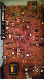
Thanks George and DF96 for some excellent advice. I'm feeling a little stupid for not reading the manual before messing around and asking questions. At any rate, the tuner has a variable muting function that can be set to 20, 30, 40 or 50db. It defaults to 30db. It can be turned off but it automatically comes back on each time a new station is tuned and must be manually turned off again, if desired.
So I can get rid of the annoying muting but it still goes in and out of stereo mode in concert with the audio level peaks. So, is it possible I still have a bad cap or does it just need an alignment?
Here is an internal photo and the subject MUTE OFF/SCAN LEVEL button
So I can get rid of the annoying muting but it still goes in and out of stereo mode in concert with the audio level peaks. So, is it possible I still have a bad cap or does it just need an alignment?
Here is an internal photo and the subject MUTE OFF/SCAN LEVEL button
Attachments

See my post 6. If you are able to follow my advice, do so. If not, find someone else who can. Do not attempt re-alignment unless you really know what you are doing and have the necessary test equipment. As I said, the most likely cause is a cap, so you just have to find it and replace it. Do not be tempted to replace every cap, or every electrolytic; that is a good method for stopping it working altogether.
DF96
Got it, thanks. I definitely was NOT going to try re-alignment. I do not have the expertise or the equipment.
How do I go about identifying the FM IF and discriminator chips(s)? I don't have a schematic ...
Got it, thanks. I definitely was NOT going to try re-alignment. I do not have the expertise or the equipment.
How do I go about identifying the FM IF and discriminator chips(s)? I don't have a schematic ...
You are welcome.
Unfortunately, I can't find the particular IC's datasheet
Inform us of any progress
George
Unfortunately, I can't find the particular IC's datasheet
Inform us of any progress
George
Well, I found the chip and pulled all (3) the electrolytics. I checked them and the values were spot on but I replaced them anyway. They are over 30 years old so that was a no-brainer.
Unfortunately, the tuner still acts the same way. I suspect it needs an alignment. Something, as I mentioned previously, I do not have the equipment to do.
Now I have a decision to make. Take it to the shop and spend probably $150-200 or just leave it the way it is or sell it. Spending that kind of money for a tuner that is probably worth only $50? doesn't make much sense...
Tweaking a discriminator coil usually isn't that hard to do. You just need to know which one of the two in a hi-fi tuner to adjust (T101, T102), and preferably do so with a non-metallic or non-magnetic tool in order not to throw off inductance. I'm not sure what sort of coils this tuner uses, maybe it's a screwdriver-friendly type already with a unit this "new".
There are two test points marked "FM off-set voltage 0 mV" here, between which you'd connect a multimeter. I suggest you do so now, you'll probably find an offset of several hundred mV.
Hi-fi tuners usually have two tunable inductors where you tend to find only one in more basic equipment. This more complex setup allows widening discriminator bandwidth and thus bringing distortion down. One of the inductors will be adjusted for minimum DC output voltage, the other for minimum distortion when using an appropriate signal generator (depending on tuner spec, it should be good to about -70 to -80 dB, or 0.03% to 0.01% THD). We are only looking to adjust the DC offset here, which thankfully brings down requirements in terms of tools a fair bit.
Going by other tuners, I think T101 should be the one we're looking for. You should be able to verify that, however, by approaching both coils with some decidedly ferromagnetic tool like a mid-size screwdriver while watching offset voltage - one should show a lot more effect. (If in doubt, mark position, watch out for effect when adjusting, and return to original position if things don't look promising.) If you don't have clip leads for the multimeter, get someone else to help you with this step.
Most people will have to make a non-metallic adjustment tool themselves, but if carving wood or plastic is not your idea of fun, a conventional screwdriver may also get the job done, though in a more tedious manner as you would have to remove it every time to check whether your alignment is OK now. Just be careful if you find inductors requiring hex tools, these are very easily damaged especially when tight.
sgrossklass,
Thanks for taking the time to not only tell me what to do but also to explain the operation - very educational.
I can handle making the tool. I have the scars on my fingertips to prove it 😎
I might even have some plastic tools made specifically for tuning but by the time I find them, I'll probably have made one from scratch;-)
I'll try this tonight and report back.
There is still hope!!!
Note that to adjust the discriminator you need to know exactly what frequency to use, which may depend on the exact centre frequency of the IF chain. It won't necessarily be 10.700MHz. depending on the ceramic filters. If AFC is on then this will try to centre the signal in the IF anyway. With FM receivers nothing is quite as simple as it seems!
If the discriminator was off-centre then you would get distorted audio, not audio-related muting. You might find that the muting region was lopsided, but the OP has not reported this as a symptom.
If the discriminator was off-centre then you would get distorted audio, not audio-related muting. You might find that the muting region was lopsided, but the OP has not reported this as a symptom.
Success!!!
I followed sgrossklass's instructions.
As he mentioned T101 was the inductor to adjust as verified by the screwdriver test prior to adjusting anything. I put the test leads on the locations specified and sure enough, there was over 500mV! I only had to give it less than a 10 degree turn (modified chopsticks make great tuner tools) to bring it as close as possible to 0mV.
I then hooked it up and confirmed that, indeed, it was no longer self-muting.
Thanks to all contributors to this thread for guiding me through this. I had resolved myself to owning a door-stop but now have a usable tuner😎
By the way although all the electrolytic caps associated with the IF chip measured ok, one did have some corrosion on the lead so I was glad to replace it.
I don't have a frequency generator so I think that is far as I can go to improve the performance. I'm so tempted to try adjusting T102 by ear for minimal distortion but I fear screwing things up...
Last edited:
I am surprised. Does the tuner not have AFC? I suppose it must have a PLL local oscillator so it can't adjust itself, unlike an old analogue tuner.
I am surprised. Does the tuner not have AFC? I suppose it must have a PLL local oscillator so it can't adjust itself, unlike an old analogue tuner.
That question is beyond my expertise. Maybe someone else can answer.
Maybe a block diagram located here http://www.fmtunerinfo.com/ST-S707block.pdf can shed some light.
Yep. It's a bog standard PLL synthesizer, by today's standards anyway (it would have been quite something to the average consumer when it came out in 1983). Complete with off-center muting, hence the issues.I am surprised. Does the tuner not have AFC? I suppose it must have a PLL local oscillator so it can't adjust itself, unlike an old analogue tuner.
Not a bad little tuner, this one, don't be fooled by its low weight. It avoids a few common pitfalls such as noisy VCO due to high series resistor for tuning diode, or excessive IF gain with limiting (the limiter amplifier in the µPC1018C is only involved after the signal has already passed 3 filters in "super narrow"). Impedance matching around the filters seems to have been less of a priority, maybe for better selectivity / reduced insertion loss?
They're using the AN7471 PLL decoder to drive a 4066 switcher. Fancy.
- Status
- Not open for further replies.
- Home
- Source & Line
- Analogue Source
- Technics ST-S707 tuner signal cutting out