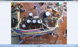
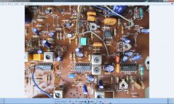
I'm repairing a Technics ST-S4 tuner. I downloaded the Technics ST-S4t service manual but its very different to what I have as in the component values etc... Anyone have a copy of the ST-S4? Or can anyone tell me what the value of resistor R709 is?(Its next to the regulator) Its burnt black and I cant make out what it is?
If you are really stuck then use empirical methods. So it seems to be in the PSU. Could it be a series feed for the reg, or a resistor supplying a bias/reference network such as a zener ? Try and determine that. If the former then it will be low value, perhaps 10 ohm or lower, if the second perhaps nearer 1k... but lets see 🙂
Knowing the above...
Measure the voltage across the resistor. Estimate the wattage of the resistor. Lets say it looks like a 1 watt part and there is 10 volts across it. That means that the resistor can't be over 100 ohm or it could never develop enough power to burn with just 10 volts available to it. If it were looking like a half watt part, then we could say not over 200 ohms or so.
That puts an upper limit on its value.
If its blackened but looks like its failed through just being under rated then it could be a an 82 ohm or there abouts.
If its a series feed resistor then it could be much much lower. Close visual examination of the circuit should show what its function is.
If you are really stuck then use empirical methods. So it seems to be in the PSU. Could it be a series feed for the reg, or a resistor supplying a bias/reference network such as a zener ? Try and determine that. If the former then it will be low value, perhaps 10 ohm or lower, if the second perhaps nearer 1k... but lets see 🙂
Knowing the above...
Measure the voltage across the resistor. Estimate the wattage of the resistor. Lets say it looks like a 1 watt part and there is 10 volts across it. That means that the resistor can't be over 100 ohm or it could never develop enough power to burn with just 10 volts available to it. If it were looking like a half watt part, then we could say not over 200 ohms or so.
That puts an upper limit on its value.
If its blackened but looks like its failed through just being under rated then it could be a an 82 ohm or there abouts.
If its a series feed resistor then it could be much much lower. Close visual examination of the circuit should show what its function is.
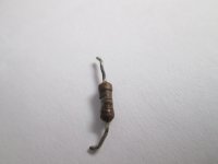
After I cleaned the resistor,I photographed it and blew it up so I could see it was brown black ?purple? gold.From past experience purple is over-cooked brown? So I put in a 100 ohm 1 watt metalized resistor? It reads 5.5v across the resistor now and the regulator reads B,12.00v. C, 15.90v. E, 11.50v. Does that seem right to you? Im just checking back before I pull it apart again?
Attachments
Last edited:
That sounds basically fine and the description seems to suggest a simple series pass regulator (NPN transistor) with a zener on its base. So lets say 6 volts across the resistor, that gives a current of 60 milliamps worst case. The resistor wattage is fine. The zener (lets assume its really a 12 volt zener) dissipates 0.72 watts worst case (0.06*12). The transistor will rob a little of that but does the zener look like a 1 watt component ? Is it very hot ? If it does run very hot then you could go a little higher on the resistor value (say 120 or 150 ohm) while monitoring the emitter voltage. Once that emitter voltage starts to fall considerably then you've gone to high with the resistor.
But yes, good work... looks like you've cracked it with the resistor.
But yes, good work... looks like you've cracked it with the resistor.
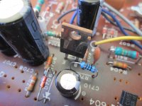
The Zener has turned out to be 6v,I can see Z6 on the side of it,and it measures 5.9v. I have installed a 470uf cap in place of a 330uf cap next to the regulator because I cant get one locally at the moment.Would that have anything to do with having no stereo light? I had a flickering stereo light previous to installing the 100 ohm resistor and the 470uf 35v cap? I measured the Vcc on chip UPC1161c (it appears to be the chip that handles the stereo light,it reads 10.7v.The datasheet says Vcc 12v? Ive got something wrong here? The regulator is a 2SD880 and of course the 6v zener,the lettering is blurry and didn't come out too well on paint.The tuner still works OK in mono though!
Attachments
The cap 470uf will have no effect on the performance. Without seeing a circuit we are guessing at the configuration of all this but I would think your repair of the 100ohm is OK as far as it all working OK goes.
Normal cause of intermittent stereo light is simple the 38kHz oscillator preset that needs a tweak... its really common across all makes and models. Give it a squirt and twizz it end to end, then set it in the middle of the pull in range on a weak signal. The preset will probably be hung off the stereo decoder chip.
Normal cause of intermittent stereo light is simple the 38kHz oscillator preset that needs a tweak... its really common across all makes and models. Give it a squirt and twizz it end to end, then set it in the middle of the pull in range on a weak signal. The preset will probably be hung off the stereo decoder chip.
The cap 470uf will have no effect on the performance. Without seeing a circuit we are guessing at the configuration of all this but I would think your repair of the 100ohm is OK as far as it all working OK goes.
Normal cause of intermittent stereo light is simple the 38kHz oscillator preset that needs a tweak... its really common across all makes and models. Give it a squirt and twizz it end to end, then set it in the middle of the pull in range on a weak signal. The preset will probably be hung off the stereo decoder chip.
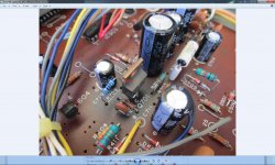
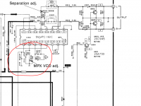
There are two VR near the stereo decoder?UPC1116c! The nearest is 500k ohms and the next one is 5k ohms? Sorry I put 50k ohms in the photo instead of 5k ohms.
Attachments
Last edited:
Hmmm... you would need to either look at a data sheet and see if that gives a clue, or just mark them with a fine felt tip and try each in turn. The lower one looks favourite.
Hmmm... you would need to either look at a data sheet and see if that gives a clue, or just mark them with a fine felt tip and try each in turn. The lower one looks favourite.
OK Ill try it and get back on how I went.Thanks for sticking with me on this Mooly.
Hmm,that didn't work? I marked them sprayed them with contact cleaner and rotated them back and forth about ten times each but there's not a glimmer from the stereo light at all,I tried it on several different stations as well?Turning the VRs had no effect on the sound either.I cant find a datasheet on this chip only the recommended sub NTE1489? I found a list of electrical characteristics for the UPC1161c stereo demodulator that's all?
Last edited:
Hmmm... put them back to where they were then.
You are going to need a manual I think. One possible complication to all of this is that if your regulated voltage has varied a little (due to replacing that resistor with something slightly different to the correct the value), then the alignment of the tuner may (may... not definite by any means) be slightly different. Whatever you do though, don't alter any of the ferrite dust cores.
If the pots haven't worked (and you must turn them really slowly to let the loop lock) then it could be a tricky one. A correct manual would help.
Hmmm... put them back to where they were then.
You are going to need a manual I think. One possible complication to all of this is that if your regulated voltage has varied a little (due to replacing that resistor with something slightly different to the correct the value), then the alignment of the tuner may (may... not definite by any means) be slightly different. Whatever you do though, don't alter any of the ferrite dust cores.
If the pots haven't worked (and you must turn them really slowly to let the loop lock) then it could be a tricky one. A correct manual would help.
OK Ill turn them slowly,if I still cant get it Ill get a manual.Heres those electrical parameters for the UCP1161c stereo modulator.I just noticed that the 500k VR has 9v on it the other one has 0.00v?
Attachments
Last edited:
Ah I see, thanks.
I was thinking more of a full data sheet with typical circuit applications shown. We do still have a question mark over the nominal 12 volts mentioned and your 10.7 actual measured. That may be absolutely normal and by design but it does need confirming by seeing the actual circuit really.
I was thinking more of a full data sheet with typical circuit applications shown. We do still have a question mark over the nominal 12 volts mentioned and your 10.7 actual measured. That may be absolutely normal and by design but it does need confirming by seeing the actual circuit really.
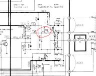
Its this one. Does your circuit not look like this. See if the resistor goes to the collector of the regulator as here (well via a 2.2 ohm).
The left schematic appears to be the correct one,the only difference being the output transistors Q602 and Q603 on mine are 2SC1815s whilst on the schematic they are 2SC945 but the right schematic is definitly different.It looks like the schematic for technics ST-S4T ,I have that but its different?
Last edited:
Yes, it was an S4T. Your 10.7 volts isn't so wide of the mark actually when you look at that circuit because there is a 47 ohm feeding the IC. The diagram shows 11.1 volts.
Yes, it was an S4T. Your 10.7 volts isn't so wide of the mark actually when you look at that circuit because there is a 47 ohm feeding the IC. The diagram shows 11.1 volts.
Yes,I remeasured the Vcc and got 11v this time. I still haven't cracked it yet with the stereo light but Ill keep trying.
Real faults on tuners can be tough. You really need a scope and frequency counter to see what's happening around the 19/38kHz oscillator. If there is any stereo/mono switching then it might be worth checking that out. Do the voltages around the chip roughly agree with the diagram ?
The voltages on the stereo demodulation chip upc1161c are roughly OK except for pin 16. Thats the stereo mono switch is supposed to be 0.1v, I measured it at 1.40v?Real faults on tuners can be tough. You really need a scope and frequency counter to see what's happening around the 19/38kHz oscillator. If there is any stereo/mono switching then it might be worth checking that out. Do the voltages around the chip roughly agree with the diagram ?
- Status
- Not open for further replies.
- Home
- Source & Line
- Digital Source
- Technics ST-S4