Question about the strobe voltage source on the SP10 MK2:
The unit I picked up last week has had the strobe light changed to an LED. It works just fine although I'm not keen on the violet colour. In any event, I have ordered a neon replacement.
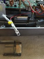
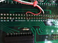
I would like to change back to a neon lamp, however the voltage presently powering the LED is tapped from a low level source on the board. The plug which powers the neon bulb is missing two wires (yellow arrows pointing to the plug), which I don't know where they have been redirected to or why.
The red & white wires going from the board to the LED presently working the strobe just fine.
Where on the board can I look for a neon bulb voltage source? I'm not very good with schematics, so I don't want to do something stupid and regret it later.
Thanks for any light (no pun intended 😀) you guys could shed on this.
Mind you, at the end of the day, I could just leave the LED and look into getting something in a different colour and intensity.
Cheers.
The unit I picked up last week has had the strobe light changed to an LED. It works just fine although I'm not keen on the violet colour. In any event, I have ordered a neon replacement.
I would like to change back to a neon lamp, however the voltage presently powering the LED is tapped from a low level source on the board. The plug which powers the neon bulb is missing two wires (yellow arrows pointing to the plug), which I don't know where they have been redirected to or why.
The red & white wires going from the board to the LED presently working the strobe just fine.
Where on the board can I look for a neon bulb voltage source? I'm not very good with schematics, so I don't want to do something stupid and regret it later.
Thanks for any light (no pun intended 😀) you guys could shed on this.
Mind you, at the end of the day, I could just leave the LED and look into getting something in a different colour and intensity.
Cheers.
Attachments
You don't say whether your unit is a Mk2 or Mk2a, but the pictures would indicate the former. Go to VinylEngine, register, and download the service manual. With that you should be able to reconstruct the Neon bulb's hookup if you desire.
You don't say whether your unit is a Mk2 or Mk2a, but the pictures would indicate the former. Go to VinylEngine, register, and download the service manual. With that you should be able to reconstruct the Neon bulb's hookup if you desire.
I mentioned that the unit is a MK2, both in the thread title, and, on the first line:
"Question about the strobe voltage source on the SP10 MK2".
And yes, I have the service manual, and I also mention I'm not very good with schematics.
Thanks just the same.
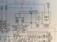
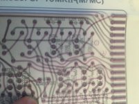
Attached is the relevant portion of the schematic, and the board layout. The purple lines on the latter are the top of the board, the other's being bottom (solder side).
There can be a few ways to do the mod, so you'll need to do some investigation. Namely, does the 140V rail of the PSU have ~140V on it? You'll also need to look at the board itself to see what, if any, modifications were done there.
If it's only the color that bothers you, the easiest way to rectify that is the swap the LED for an amber one.
Attachments
Thanks allot JP, really appreciate your effort.
Maybe I'll stick with the LED, different colour. What voltage should I be looking at for a new LED?
And, is it ok to use a festoon LED?
Maybe I'll stick with the LED, different colour. What voltage should I be looking at for a new LED?
And, is it ok to use a festoon LED?
Last edited:
It is unlikely that the LED would be running at its maximum permissible current, the current would be limited to something in the order of 5mA. With this in mind any similar LED would work with no modifications.
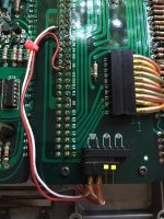
My primary concern with a festoon LED is current - how much does it draw, and can the circuit supply it. In order to figure that out, you'd need to go over the modification and figure out where they tapped in to supply the LED.
My primary concern with a festoon LED is current - how much does it draw, and can the circuit supply it. In order to figure that out, you'd need to go over the modification and figure out where they tapped in to supply the LED.
Here:
Attachments
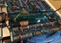
Wrong end of the equation. The mod is going to be in the area of the board I pictured.
Gotcha.
I'll take the sucker apart again this weekend.
Thanks.
I read it wrong - I thought it was 0V and N1, not 5V and N1. My guess is the mod is just lifting C1, either in the table or at the PSU.
- Status
- Not open for further replies.
- Home
- Source & Line
- Analogue Source
- Technics SP10 MK2 neon strobe voltage source?