Can it be just a regular 2v 20ma led?
Yes, that's right.
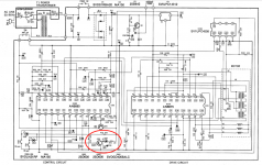
The switch transistor connects the LED's cathode to ground through a 120R resistor from 12VDC.
Last edited:
Thanks Rama for your answer. What makes it harder to under to understand for me is the transistor. It seems that the LED is only "seeing" 12-6=6 volts? the service manual says I should measure 6volts at TP26 this is the led minus. If I calculate the dropping resistor for my LED 2v 20mA. I get 200ohm not 120ohm. Am I correct?
Thanks Rama for your answer. What makes it harder to under to understand for me is the transistor.
It seems that the LED is only "seeing" 12-6=6 volts? the service manual says I should measure
6volts at TP26 this is the led minus. If I calculate the dropping resistor for my LED 2v 20mA.
I get 200ohm not 120ohm. Am I correct?
When the LED is on, the Q will be saturated with a collector voltage of around 0.1VDC.
When the Q is off, the collector voltage should be 12V because of the open circuit.
The value of the dropping resistor is not critical, it just limits the current to some
reasonable value, (12V-2V)/120R = 8mA in this case.
It may be that the 6VDC is the average voltage reading, since it switches alternately
between 12V with the Q off, and 0V with the Q on. Can you post a link to the service manual?
Last edited:
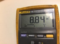
No I don't have a direct link, I downloaded it at the VinylEngine. I did measure again and it varies but the average is 8.84volts
No I don't have a direct link, I downloaded it at the VinylEngine.
I did measure again and it varies but the average is 8.84volts
If the LED is working (turning on and off) it should be ok. If not, the driver transistor,
or even the IC, may be bad. If a new LED does not work, try replacing the transistor.
Do you have a scope?
Last edited:
> It seems that the LED is only "seeing" 12-6=6 volts?
This is a strobe. More than likely, the strobe marks are half-and-half, and the strobe light blinks 50:50. Probably somewhere near 50/60Hz, because that gives a reasonable number of marks.
If the transistor collector is at 12V half the time, and zero (maybe 0.2V) the other half, at a rate too fast for a DC meter to follow, the meter will say this point is 6V.
> average is 8.84volts
Agree-- suspect the transistor.
Quick check: put about 1K from TP26 to ground. That should light the LED, even if the transistor is dead. (It won't "strobe", just light.)
> (12V-2V)/120R = 8mA in this case.
One of us has sticky dots in our slide-rule. I get 85mA when on, 43mA average.
Attachments
Last edited:
One of us has sticky dots in our slide-rule. I get 85mA when on, 43mA average.
That's right, so maybe it's a high brightness type of LED that can take more current.
http://www.farnell.com/datasheets/1...7.1444573703.1504304474-1491211110.1504304474
Other models of this TT use multiple LEDs in a chain, with a higher supply voltage.
Last edited:
Ok, this is great stuff I'm learning things here 🙂 Thanks for your replies!
I've already put in the LED I ordered. specs are 1.8->2.2V and 20mA -> 30 mA
it works, but very very bright. The package says "super bright" so just to be sure I asked the question if I could use any basic LED as replacement.
Originaly the Q202 is a 2SD636 transistor, It was missing so I replaced it. Sorry to only mention this now, this is a slow project for me and I have only worked on this a few times this year.
I couldn't find the 2SD636 but in the Fairchild cross reference guide I found the KSC945. I had another look around and also ordered the 2N3904. I've tried them both and they both measure the same 8.84V.
I do have a scope. I've bought it a few years back, but haven't had much time to play with it and found out how to put it to use. Maybe it's time to get it out of the attic and try again.
-->One of us has sticky dots in our slide-rule. I get 85mA when on, 43mA average.
So I could still use the LED's I have but them in series.
Do I uses the 85mA and use 4 or do I use the average 43mA and use 2?
Attachments
When it comes to modern high brightness LED's you will find they are blindingly bright compared to stuff of years ago.
Trial and error is the key. You could well find 10k is needed (yes 10k) with a modern part. Start high and work down to get the brightness that suits you.
Q202 should be a high gain device (small signal BC or 2N type) as it would appear that the base drive is limited by the driving chips output port.
> Q202 ..., It was missing
Works better if it is there.
> find the 2SD636
It isn't a magic part. As your test shows, essentially any NPN will do. On this side of the pond, 2N3904 would be routine. 2SD636 may just have been over-stocked the day Technics designed this.
> a high gain device
Well, good gain. Such mini-CPUs will usually put 2mA to a naked Base, so with original current values we need Beta > 45. Rare to find one under 100.
> works, but very very bright.
I thought I had wrote this, but I see the internet (or my fat fingers) dropped it.
With modern LEDs you do not need 85mA blinks. As Mooly says, the "120r" could be a lot bigger for happy brightness. And less stress on Q202 and LED.
I assume the LED is not on the PCB, or that you can remove it and run wires. In one of those wires add another few K Ohms of resistance. I say at least 1K (to keep current down to 10mA which should be bright yet well below any 20mA rating). I know that many guitar pedal builders are going to 10K and more for LED resistors so their pedals don't blind them (or leave extra-note afterimage dots on the score). Just tack-solder 5K or 10K and see how it looks.
Attachments
- Status
- Not open for further replies.
- Home
- Source & Line
- Analogue Source
- Technics SL-Q2 strobe led replacement