Dear friends. I am seek your help in getting my Technics SL D2 (Direct Drive), semi-automatic turntable playing.
I have checked almost everything. Found nothing unusual.
Motor is lube with no resistance while hand spin.
• Transformer : output 28.6V
• S2 Speed selector - check
• all Capacitor - check
• all Resistor - check
• Rectifier - check
• Q1 (2SC1846) B-22V, C- 35.8V, E- 21.4V reading taking with (S1-ON, S2-33)
• Q2 (2SD637) B-21.9V, C- 35.8V, E- 22.1V (S1-ON, S2-33)
• Q3 (2SB641) B-17.62V, C- 3.8V, E- 18.52V (S1-ON, S2-33)
• C1 across - DC35.6V
Verify speed select switch is not in neutral position.
EDIT: Oh, you already mentioned that... Sorry.
EDIT: Oh, you already mentioned that... Sorry.
This's a three phase syncronous motor similar to those I found in 5.25in diskette drivers. You will need a good oscilloscope and test every waveform to find where the problem starts.
I would start recaping the most important small 1 and 2.2uF. They may be leacky or dryed and some of them are important.
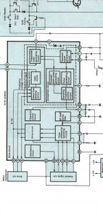
The schematic is clear, there is an oscillator at pins 1 and 24. Possibly this frequency be a 3x multiple of final frequency aplied to the stator coils. Thus there are some pick up coils that "sees" the rotor speed (frequency) and applies more current to the rotor in order to increase or decrease torque according to a fixed signal whose frequency is defined by the pots at pin 24.
Note that the current in a coil decreases as the frequency is increased at constant voltage, thus to mantain torque the voltage and the frequency must be varied mantaining its ratio constant. Possibly this increase of current be done by means of increasing PWM duty to the rotor.
Without an oscilloscope it will be very difficult task. In extreme case change the IC too.
I would start recaping the most important small 1 and 2.2uF. They may be leacky or dryed and some of them are important.
The schematic is clear, there is an oscillator at pins 1 and 24. Possibly this frequency be a 3x multiple of final frequency aplied to the stator coils. Thus there are some pick up coils that "sees" the rotor speed (frequency) and applies more current to the rotor in order to increase or decrease torque according to a fixed signal whose frequency is defined by the pots at pin 24.
Note that the current in a coil decreases as the frequency is increased at constant voltage, thus to mantain torque the voltage and the frequency must be varied mantaining its ratio constant. Possibly this increase of current be done by means of increasing PWM duty to the rotor.
Without an oscilloscope it will be very difficult task. In extreme case change the IC too.
Hi Osvaldo, Good morning, I have checked all the cap they are all reading OK except C3 It measure 0.44uf (schematic 0.22uf) and I replace to 0.1uf. Tested motor not spin. I do not have a oscilloscope & not sure how to use it. I suspect the IC AN630U is bad. I have another working SL-D2. will swap the IC AN630U & test it. Thanks for your advice & informations. 🙂This's a three phase syncronous motor similar to those I found in 5.25in diskette drivers. You will need a good oscilloscope and test every waveform to find where the problem starts.
I would start recaping the most important small 1 and 2.2uF. They may be leacky or dryed and some of them are important.
The schematic is clear, there is an oscillator at pins 1 and 24. Possibly this frequency be a 3x multiple of final frequency aplied to the stator coils. Thus there are some pick up coils that "sees" the rotor speed (frequency) and applies more current to the rotor in order to increase or decrease torque according to a fixed signal whose frequency is defined by the pots at pin 24.
Note that the current in a coil decreases as the frequency is increased at constant voltage, thus to mantain torque the voltage and the frequency must be varied mantaining its ratio constant. Possibly this increase of current be done by means of increasing PWM duty to the rotor.
Without an oscilloscope it will be very difficult task. In extreme case change the IC too.
Last edited:
Hi Rick, Yes I do, The light is ON. But not spinning. I have been using it since 2019 (gift by my uncle). Few days ago it suddenly stop spinning while playing.Have you moved the arm towards the turntable to turn it on?
Hi 6L6, The switch checked. Is working.Verify speed select switch is not in neutral position.
EDIT: Oh, you already mentioned that... Sorry.
Hi RS232, Platter not spinning when the strobe light is ON.What exactly is wrong with it ?
Hi Rick, How to do it? Can it be done by multimeter?You can also measure the AC across C1 to check the amount of ripple to check the diodes.
There are calculators to determine what ripple should be. I'm betting it's pulling between 10 and 100mA with the platter not turning. With the 470uF cap, and 100mA draw and 60Hz, you would expect 1.25VAC ripple. If you have more than that you more than likely have a bad diode.
- Home
- Source & Line
- Analogue Source
- Technics SL-D2 Light on platter not spinning. Help