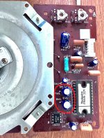
I recently acquired an all original Technics SL-6 at a bargain price. It performs well but not flawlessly, and a quick check of the electrolytics suggests their replacement might be a good idea. Considering those caps are now pushing 40 years old (the plastic cover has a 1983 date code), it's probable that they're now at the ends of their operational lives.
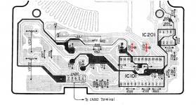
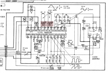
Ordinarily this would be a piece of cake, but there are two 47 uF 16 V non-polar electrolytic caps across the stator coils as shown in the attached files. There's no exact replacement available at the usual suspects (Mouser, Digi-Key, etc.), so as I see it, I'm faced with executing the least worst of several unsavory options. They are (listed in no particular order):
BTW, I understand there are some who take the "if it ain't broke, don't fix it" approach, and I respect that. But that's another topic for another thread.
Thanks!
Ordinarily this would be a piece of cake, but there are two 47 uF 16 V non-polar electrolytic caps across the stator coils as shown in the attached files. There's no exact replacement available at the usual suspects (Mouser, Digi-Key, etc.), so as I see it, I'm faced with executing the least worst of several unsavory options. They are (listed in no particular order):
- Do nothing. Pros: Cheap,
EasyLazy; Readily available (as laziness tends to be). Cons: Failure in the near future likely; Subsequent destruction of motor driver IC likely (used AN6636 ICs are difficult to source at best). - Replace each with two 100 uF @ 16 V polar electrolytics bodged "+ to +" or "- to -". Pros: Cheap; Easy to source; Likely to fit. Cons: Ugly; Lots of conflicting advice regarding advisability and long-term reliability.
- Replace each with one 47 uF @ 50 V film. Pros: Readily available; Permanent fix. Cons: Minimum voltage of 50 V is 3X over spec; Off board mounting required (no space); Relatively expensive; Mechanically less robust.
- Replace each with one 47 uF @ 16 V dipped ceramic. Pros: Cheap; Easy; Likely to fit well. Cons: Possible issues regarding differences in ESR between the types; Lots of conflicting advice regarding advisability of the practice.
- Replace each with one 47 uF @ 16 V bipolar/nonpolar Electrolytic (Surface Mount). Pros: Cheap; Readily available; Electronically mirrors existing installation. Cons: Ugly; Will need to bodge wires to solder pads; Mechanically less robust.
- Replace each with one 47 uF @ 100 V bipolar/nonpolar Electrolytic (crossover type). Pros: Cheap; Readily available; More or less electronically mirrors existing installation. Cons: Off board mounting required (no space); Mechanically less robust; Lifetime and temperature rating unknown.
BTW, I understand there are some who take the "if it ain't broke, don't fix it" approach, and I respect that. But that's another topic for another thread.
Thanks!
Attachments
I agree with the option 5 as more effective, but trying to solder it under the PCB as it would be a SMD. No need to solder any wire. My opinion only: I did it several times when replacing starting capacitors in SMPS by the newer MLCC directly under the PCB, in the same site as the (erased) old lytic.
That's where I was leaning, but without considering the possibility of mounting the replacements on the reverse side (D'OH!!!). That's an excellent idea, but I doubt the space will be available because that board is mounted upside down with the reverse nearly flush with the top deck. It's worth measuring to be sure, though. Thanks!
It seems to me from the second pic that nothing is under the caps on question. A MLCC cap will use +/- the same space as the solder blobs plus the wire remanent underside. In any case you can put 3 caps of 15uF in parallel along the tracks removing the solder mask (if any) and 15uF units surely are smaller than 47uF.
Won't one of these work?
https://www.mouser.com/c/passive-co...es&capacitance=47 uF&voltage rating dc=25 VDC
https://www.mouser.com/c/passive-co...es&capacitance=47 uF&voltage rating dc=25 VDC
Double check the lead spacing, hole diameter, and body diameter (and height if necessary).
The UES parts are excellent. Use the 25V or 35V parts if possible, instead of the 16V.
The UES parts are excellent. Use the 25V or 35V parts if possible, instead of the 16V.
Will do! I compare the geometries between the old and new as a matter of course. Normally the spacing between components on '70s era equipment allows for ample adjustment for newer components, but this turntable is particularly tight (even considering the reduction in part sizes over the past several decades). BTW, that photograph to which Osvaldo referred is deceptive; I photographed the stator assembly it as it lay on the workbench after removal from the unit.
Anyway, thanks for pointing me in the right direction and the reassurance regarding the part quality.
I still can't get over having missed those... D'Oh!!
Anyway, thanks for pointing me in the right direction and the reassurance regarding the part quality.
I still can't get over having missed those... D'Oh!!
- Home
- Source & Line
- Analogue Source
- Technics SL-6 Bipolar Electrolytic Conundrum