Hi all. Just finished repair of A1 with blown channel. Going through after-repair adjustments I am unsure which bias shall be sufficient for Class-A section. In absence of service manual, what we have there is just emitter resistor 0.68 ohm per device, showing 0,8volts across both resistors (emitter to emitter). Simple calculation is 0.8/(0,68+0,68)=0.588 times 8 - there are eight pairs of output devices. Got 4,7 ampere in total or 0.6A per pair. Rails are +/- 10V. Low? High? Or its normal? Maybe someone have working amp and be so kind to measure?
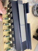
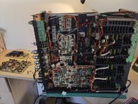
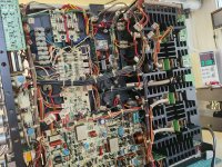
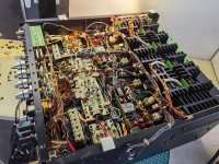
some pics just for reference
some pics just for reference
Attachments


Thank you. The voltages on the bases of output devices on this drawing seems to be even higher (+/-1.9v) at r424/r425, I measure +/-1.45v on mine. Nevertheless, I would feel much comfortable measuring voltage drop across emitter resistor just to have absolute number of amperes going through the output
Hello, the voltage at the A part on the A board should be between 0.9 and 1.0 Volt at TP501. You can adjust this voltag on VR 402 on the left and right SUP 13170 board. Then the sum current of all transistors is about 6.5 Ampere.
Dieter
Dieter
Attachments
Last edited: