Follow the circuit back from the bases of the D1302s. It will likely go back through a resistor or two and possibly to an A1381 (transistor).
If that's true, follow the circuit back from the base of the A1381. What drives that transistor?
If that's true, follow the circuit back from the base of the A1381. What drives that transistor?
You stated that the square wave on the outputs is switching on and off. Does the current draw decrease when it's off?
OPPPSSS followed the wrong leg back .
The A1381 is driven by a C1027 Transistor heres the voltages on it
Leg1:0.00
Leg2:7.25
Leg3:0.00
The A1381 is driven by a C1027 Transistor heres the voltages on it
Leg1:0.00
Leg2:7.25
Leg3:0.00
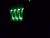
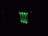
The square wave is still pulsing with the A1381 and C1027 removed .
Also the voltages on the rectifiers is pulsing
Also the voltages on the rectifiers is pulsing
Is the power supply remaining on? Look at the square wave on the drain/tab of the power supply FETs.
OK. That seems to eliminate the protection components on the main board.
On the audio driver board, on the center row of pins, one end pin has 15v. Sso you know that you have the right pin, confirm that it has 15v. On the other end of that row, do you see a pulsing output?
On the audio driver board, on the center row of pins, one end pin has 15v. Sso you know that you have the right pin, confirm that it has 15v. On the other end of that row, do you see a pulsing output?
Do you have both positive and negative rail voltage?
Do you have the proper output voltage on all of the regulators? Place the black probe on the 'ground' pin of each regulator when measuring the voltage. The 78xx ground is the center leg. The 79xx ground is the first leg.
Do you have the proper output voltage on all of the regulators? Place the black probe on the 'ground' pin of each regulator when measuring the voltage. The 78xx ground is the center leg. The 79xx ground is the first leg.
- Status
- Not open for further replies.
- Home
- General Interest
- Car Audio
- Team Cactus 7kw