mircasi said:Hello,
I have a problem with my TEAC VRDS10
The motor refuse to work, so the cd's never recognized.
So if someone may send me the schematics, it would help me 🙄
Tanhks
Maël

The majority of problems (90% I’d say) stem from two small rubber pulley belts on the Vrds 10/20’s. (These are the Achille’s heels of the units) One is for the drawer, the easy one to access.
If the belts are old and just slipping the problems can be intermittent, if they have broke or slipped off the pulleys then the units refuse to function.
In any case both belts should be placed with belts of similar size, the new ones will be smaller than the old ones which have stretched and dried out over time (10+ years).
The other belt is for the mechanical lift, which lifts and lowers the CD to the clamp which engages the drive system, other wise you get an error that the cd is not inserted or spins radically (no eject or play). This belt is difficult to access and needs a lot of disassembly (service manual recommended from Teac or online).
Most service centers will insist your laser is gone and is usually not the case, unless the mechanical part of the laser assembly is malfunctioning the laser should almost last forever, contrary to popular opinion
Once the unit is apart take the time to lubricate what you can with tiny drops of light oil, especially the shafts, make sure you do not get any lubricant on the belts and wheels. Use a silicone grease on the drawer guides.
This should help.
VRDS 10 schematics and service manual
Hi everybody here , i'm a new user just registered today !
I actually own a Teac VRDS10 cd player 10 years old and in perfect shape . I've heard (and its a reason why i've bought it ) that it was one of the best existing CD drives , but not really outstanding concerning the electronic part.. i would like to upgrade it and get the utmost quality i can get from it ..
can any one help me finding the service manual and complete schematics first . then give me links or advises about how to tweak it properly (clock, power supplies , analogic output ..)
i wonder what could be better: upgrade the existing internal pcbs or plug it to an external dac ...
thanks very mutch
VRDS-10
A Tent-clock (XO3) with recloking (out on a separate BNC) should get the most out of it.
Arne K
A Tent-clock (XO3) with recloking (out on a separate BNC) should get the most out of it.
Arne K
Thanks ARne !
i've heard of this reclocking tricks there are several kits :
LCaudio ,audiocom, tentlabs(tentclock is from there i think ) , DIY "kwakclock", selectronic clock: is one of them better ?
what do u mean by reclocking "on an external bnc" does that mean i should use an axternal DAC ?
thanks
i've heard of this reclocking tricks there are several kits :
LCaudio ,audiocom, tentlabs(tentclock is from there i think ) , DIY "kwakclock", selectronic clock: is one of them better ?
what do u mean by reclocking "on an external bnc" does that mean i should use an axternal DAC ?
thanks
Hallo Andreas,
could you send me the schematic by mail ?
Danke
Gruss
Pascal
PS: I ordered two Elna 4700µF capacitors to replace Digital PSU capacitors (3300µF and 4700µF). It seems that the improvement is near the result you have if you reclock, and just with 2 capacitors.
could you send me the schematic by mail ?
Danke
Gruss
Pascal
PS: I ordered two Elna 4700µF capacitors to replace Digital PSU capacitors (3300µF and 4700µF). It seems that the improvement is near the result you have if you reclock, and just with 2 capacitors.
Teac VRDS 10 repair & schematic
Hi all,
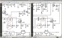
I recently acquired a TEAC VRDS10 as a cd transport. Though it is working, I found that on the Audio PCB, power supply area resistor R101 is broken with burnt marks on PCB. Could anyone advise the value or if possible provide me a copy of schematic?
Secondly, which tweak do you find, give the most improvement to the TEAC? A very frank clock maker advises against just changing the stock cystal osc with a 'low jitter clock' saying it is a waste of time and money if the unit is going to be used as a transport as the problem is with jitter at DAC end. Those 'clocks' were meant for cdp and not transports. For transports, the 'sychronizing' of the clocking at DAC end is far more complicated.
Anyone done tweaking on the digital output end like new BNC/RCA connector, coupling capacitor with good results? What about power supply tweaks?
Thanks in advance. Best Regards. 🙂
Hi all,
I recently acquired a TEAC VRDS10 as a cd transport. Though it is working, I found that on the Audio PCB, power supply area resistor R101 is broken with burnt marks on PCB. Could anyone advise the value or if possible provide me a copy of schematic?
Secondly, which tweak do you find, give the most improvement to the TEAC? A very frank clock maker advises against just changing the stock cystal osc with a 'low jitter clock' saying it is a waste of time and money if the unit is going to be used as a transport as the problem is with jitter at DAC end. Those 'clocks' were meant for cdp and not transports. For transports, the 'sychronizing' of the clocking at DAC end is far more complicated.
Anyone done tweaking on the digital output end like new BNC/RCA connector, coupling capacitor with good results? What about power supply tweaks?
Thanks in advance. Best Regards. 🙂
I have a TEAC VRDS-T1 drive.
There is no clock in my audionote DAC.
This is the clock of the drive who build the digital signal ... and the jitter.
I have change the clock (selectronic TCXO) and the result is incredible.
An other good tweak is to change the SP/DIF digital output, the resultat is surprising ! (I used the ASE-Audiotuning module)
And you can also change the 2 big capacitors on the alimentation by Low ESR capacitors.
I have a VRDS 20 that I converted to transport only. I added 3 Audiocom Invisus regulators and that made a big improvement.
I will be putting in a Superclock soon. My external dac had clocks built in for recording and USB use but it still uses the clock in the VRDS when I use SPDIF connection. The clock in the VRDS is ok and the Invisus reg helps but I am sure that the dedicated clock will be miles ahead. FWIW my memory player PC based server still smokes any transport I have used.
Bob
dht 4 me said:My external dac had clocks built in for recording and USB use but it still uses the clock in the VRDS when I use SPDIF connection. Bob
It doesn't. It uses a silicon based clock, which usually is inside the input receiver, and synchronised using the SPDIF datastream. Needless to say that clock isn't half as good as what's inside the TEAC. See confirming measurements:
http://members.chello.nl/~m.heijligers/DAChtml/Measurements.htm
and notice 30dB difference in quality
best
when the dac is plugged into usb the internal clock sync LED is lit.
When the SPDIF is plugged in the external clock sync LED is lit.
This is primarily a USB dac and I don't recall seeing the Crystal semi input reciever.
So what are you telling me.
it syncs to a reconstructed clock internally?
When the SPDIF is plugged in the external clock sync LED is lit.
This is primarily a USB dac and I don't recall seeing the Crystal semi input reciever.
So what are you telling me.
it syncs to a reconstructed clock internally?
dht 4 me said:when the dac is plugged into usb the internal clock sync LED is lit.
When the SPDIF is plugged in the external clock sync LED is lit.
This is primarily a USB dac and I don't recall seeing the Crystal semi input reciever.
So what are you telling me.
it syncs to a reconstructed clock internally?
how else would you regenerate a clock from an SPDIF signal ?
best
then it is fairly obvious to me that it is still reliant on the clock inside the VRDS as I has said originally .
The clock in the VRDS is ok and the Invisus reg helps but I am sure that the dedicated clock will be miles ahead.
dht 4 me said:then it is fairly obvious to me that it is still reliant on the clock inside the VRDS as I has said originally .
Yes, it does rely on the drive clock (but the recovered clock will never be as good, one needs a secondary PLL to achieve that)
best
Guido,
Have you a solution to replace the regulators on the VRDS-T1 ?
NJM78M05FA and NJM79M05FA used are done for 5V/500ma.
Your shunt regulator in 5V version is only 80ma, is it enought ?
Thanks
Henri
Have you a solution to replace the regulators on the VRDS-T1 ?
NJM78M05FA and NJM79M05FA used are done for 5V/500ma.
Your shunt regulator in 5V version is only 80ma, is it enought ?
Thanks
Henri
bobbyw said:Guido,
Have you a solution to replace the regulators on the VRDS-T1 ?
NJM78M05FA and NJM79M05FA used are done for 5V/500ma.
Your shunt regulator in 5V version is only 80ma, is it enought ?
Thanks
Henri
Hi Henri
Ina drive, the use of these regs is very likely for the servo's. It doesn't make sense to replace these, I'd suggest to spend money on the clock
best
Hi Guido,
Ok thanks.
I think it was a good tweak after changing the clock and the SP/DIF output module because dht 4 me said
I will contact you for Tube filament supply for my PP845 monoblocs.
Henri
Ok thanks.
I think it was a good tweak after changing the clock and the SP/DIF output module because dht 4 me said
I have a VRDS 20 that I converted to transport only. I added 3 Audiocom Invisus regulators and that made a big improvement.
I will contact you for Tube filament supply for my PP845 monoblocs.
Henri
Hi all,
I recently acquired a TEAC VRDS10 as a cd transport. Though it is working, I found that on the Audio PCB, power supply area resistor R101 is broken with burnt marks on PCB. Could anyone advise the value or if possible provide me a copy of schematic?
Secondly, which tweak do you find, give the most improvement to the TEAC? A very frank clock maker advises against just changing the stock cystal osc with a 'low jitter clock' saying it is a waste of time and money if the unit is going to be used as a transport as the problem is with jitter at DAC end. Those 'clocks' were meant for cdp and not transports. For transports, the 'sychronizing' of the clocking at DAC end is far more complicated.
Anyone done tweaking on the digital output end like new BNC/RCA connector, coupling capacitor with good results? What about power supply tweaks?
Thanks in advance. Best Regards. 🙂
Maybe old tread but help on the resistor question.
THe resistor in the vrds10 has been a fault from TEAC, in the vrds10SE
The parts are very much the same but they change the resistor into higher ohms (course there was too much current running)
In vrds10 the resistor 101 is 220 ohms but you need to change it to 1K
So there is 5 times less current running and resistor gets with 220 much to hot.
I noticed it had the same with the 10 and i have a 10se too ....
I have the service manuals on ebay one guy is actually selling it on pdf
Hmm must be getting rich of it. Rip off if i may say it🙁
So here is the solution to your teac resistor question 😀
Visit my page about the teac tweaks
Teac vrds 10 SE - Dutchamps
Tweaks like :
Changing rca to bnc (gives hudge improvements with depth and widths in stereo is far greater )
Changing capasitors in the digital part (gives more precise imaging and stereo focusing)
Building in the tentlabs clock ( still busy with it to get it right, need Guido`s input )
There are email addresses available via my website 😀
Attachments
Last edited:
Hi all,
Secondly, which tweak do you find, give the most improvement to the TEAC? A very frank clock maker advises against just changing the stock cystal osc with a 'low jitter clock' saying it is a waste of time and money if the unit is going to be used as a transport as the problem is with jitter at DAC end. Those 'clocks' were meant for cdp and not transports. For transports, the 'sychronizing' of the clocking at DAC end is far more complicated.
Thanks in advance. Best Regards. 🙂
This clock master should do some jitter measurements and study the average PLL applied in external DACs. Simple measurements show that he is wrong:
Measurements
Modern samle rate converters are much better in suppressing incoming jitter, but need care to perform right.
best
- Status
- Not open for further replies.
- Home
- Source & Line
- Digital Source
- Teac vrds 10 service help needed