Does someone have schematic for analog output..
http://www.ti.com/lit/ds/symlink/pcm1795.pdf examples in page 39-40 looks different compared to what we have in box.. I don't understand part for green caps..
http://www.ti.com/lit/ds/symlink/pcm1795.pdf examples in page 39-40 looks different compared to what we have in box.. I don't understand part for green caps..
Attachments
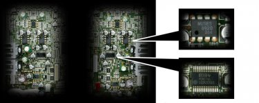
Not really easy to see, but it looks quite similar to me. The socketed MUSES opamps are the differential stage and the SMD opamp is the BAL/SE conversion. Wild guess is that the green caps on top are in the SE signal path to prevent any DC from reaching the outputs.
/U.
/U.
Mine too..Wild guess is that the green caps on top are in the SE signal path to prevent any DC from reaching the outputs.
But why, if the manufacturer does not see any need for that..
Maybe a "belt and braces" approach to ensure that downstream equipment is protected in case of failures? Those two caps cost very little to add. Another possibility is that TEAC are using bipolar opamps which introduce a bit of offset on their own that must be removed.
/U.
/U.

- Status
- Not open for further replies.