I've been using an LCR-T4 Digital Tester.The DCR readings on the original coils form post#50 seem way too high. The woofers inductor should have been getting very hot if so. Its bobbin size does not imply that high a DCR. Also the small coil appears close in DCR to the big one and that's fishy too. See alike coils typical DCR
How you got their mH? You have a DMM that reads inductance too? By the way since you are a speakers hobbyist maybe get a DATS V3 interface at a point. Measures not only the drivers T/S parameters but inductors and capacitors too in a proper way for audio band use.
There are no off the shelf such nominal inductance values for air core inductors. But there are tolerances. Being thorough, Vikash either noted down the replacement air core exact unit values or the original coils unit values. Most possibly by using an LCR meter set at 1kHz. 0.65mH vs 0.633mH is 2.7% tolerance. Not critical.
Last but not least we don't know what Vikash found for original coils DCR but we know that he used air core replacement coils similar to your order and he ended up with a correct loudspeaker response result.
It's been very accurate with Capacitors.
I've tested at least 20 Poly caps purchased new and readings using this tester were pretty well spot on.
It automatically decides what is connected and then produces a read out accordingly.
When testing these Inductors it displayed both resistance & mH readings.
I recall using it to test Inductors I purchased for a previous project and readings agreed with the sales spec.
Without knowing the correct values of original Inductors, would you say that Vikash's specifications should yield a positive outcome?
The replacement Inductors are advertised as having a 3% or less tolerance.
I have such a tester too and I run it on a random air-core coil to help the discussion. It shows 0.4mH 0.7Ω in the picture for a 0.45mH 0.57Ω as tested on my calibrated DER-EE LCR meter at 1kHz and then DC. Using Kelvin clips. Thus the little device with the nice bright screen could be systematically showing smaller enough inductance due to test frequency or method differences. The R shown while not precise by tending higher it isn't wild either.
Attachments
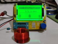
By the way: Try to avoid using wire extensions to the component tester especially when for LCR purposes. If using any they should be 10cm short and thick gauge. Typical super cheap crocodile leads or breadboard jumpers have a hair of recycled blackened something pretending the wire inside that can measure into enough Ohms range alone.
Yes, its all we got to depend upon backed with a frequency measurement result and his independent subjective assessment. They maybe changed the coils and resistor values a bit during the production run and Vikash could have met different original components to a degree but the drivers and cabinet are the same. The way they put together the factory crossover with the burn a hole to the planet's core resistor, why they could be trusted at all for they kept a crossover consistency standard better than Vikash's I don't know.Without knowing the correct values of original Inductors, would you say that Vikash's specifications should yield a positive outcome?
The crossover parts arrived today and I'm now focusing on the layout.TDL RTL Rebuild - Crossover and Measurements
Yes, its all we got to depend upon backed with a frequency measurement result and his independent subjective assessment. They maybe changed the coils and resistor values a bit during the production run and Vikash could have met different original components to a degree but the drivers and cabinet are the same. The way they put together the factory crossover with the burn a hole to the planet's core resistor, why they could be trusted at all for they kept a crossover consistency standard better than Vikash's I don't know.
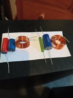
Vikash has placed his Inductors at 90 degrees to each other but are very close.
My Inductors are bare iron core copper without the drum and wrapping displayed on Vikash's examples.
I'm keen to build on the back of the terminal plate.
Is 90 degrees but very close suitable?
Should I insulate them in some way to avoid touching?
How would I fix them so they are firmly in position (apart from being stacked together with other parts, I can't see which method Vikash has used)?
Also there appear to be small orange colored components to the right side of the upright resistor. I'm wondering what these are?
thanks Cliff
Vibration may cause them to wear off their enamel and cause further problems.Should I insulate them in some way to avoid touching?
The small orange components are little resistors he used in series to compose a value he missed. Don't take Vikash's crossover build photo as a guide. It does not appear optimal. Look into Troels's end of page placement conclusions instead: http://www.troelsgravesen.dk/coils.htmThe crossover parts arrived today and I'm now focusing on the layout.
Vikash has placed his Inductors at 90 degrees to each other but are very close.
My Inductors are bare iron core copper without the drum and wrapping displayed on Vikash's examples.
I'm keen to build on the back of the terminal plate.
Is 90 degrees but very close suitable?
Should I insulate them in some way to avoid touching?
How would I fix them so they are firmly in position (apart from being stacked together with other parts, I can't see which method Vikash has used)?
Also there appear to be small orange colored components to the right side of the upright resistor. I'm wondering what these are?
thanks Cliff
Thanks Salas.The small orange components are little resistors he used in series to compose a value he missed. Don't take Vikash's crossover build photo as a guide. It does not appear optimal. Look into Troels's end of page placement conclusions instead: http://www.troelsgravesen.dk/coils.htm
The separation distances Troal advises for the Inductors (example 20cms), are they centre of air core to centre of air core, or between outer edges of Inductors?
I can see a ruler in his pictures. Its left side pointing at an inductor's centre. So distances mentioned should be core to core.
Thanks.I can see a ruler in his pictures. Its left side pointing at an inductor's centre. So distances mentioned should be core to core.
Originally I was going to copy Vikashs crossover but after your input, I'll be keeping away from the terminal backplate and will create a separate crossover with enough real estate for optimal orientation.
Its the best option. Will be reducing coils crosstalk. Is there a picture of the replacement parts you bought?
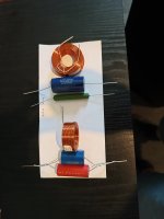
The first 2 pics are stage 1 (33Ω Resistor for the woofers)Its the best option. Will be reducing coils crosstalk. Is there a picture of the replacement parts you bought?
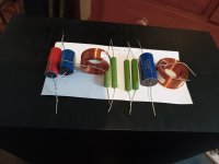
The last 2 pics are stage 2 (22Ω & 18Ω Resistors in parallel to replace the 33Ω, & RP1 1Ω, & RP2 10Ω for the tweeter)
The 6µF Cap requirement for Tweeter is made up of 5.6µF Standard Z & 0.47µF Superior Z (bypass style).
The paper they're sitting on is 95mm x 200mm.
This size will slide into the rear terminal pad opening, but I suspect it will be a trial to fasten it to the sidewall as there is no room for drill.
Also, are Inductor terminals polarity conscious?
Is there a protocol when using Inductor (terminal wire off inside of coil vs terminal wire on outside of coil)?
Attachments

Last edited:
How far are the coil cores in this mockup?
No there are no polarity rules for coils. Just apply the same wiring convention in a build. Say input is off inside.
No there are no polarity rules for coils. Just apply the same wiring convention in a build. Say input is off inside.
You could also assemble in two portions. To end up with easier to install filter sizes.
Say the LF filter at the back of the terminals frame and the HF filter on a board mounted inside. Or vice versa.
It's a bi-wire terminals set already so it helps separate wiring. Coils will end up super separate too in this case.
Say the LF filter at the back of the terminals frame and the HF filter on a board mounted inside. Or vice versa.
It's a bi-wire terminals set already so it helps separate wiring. Coils will end up super separate too in this case.
Hmm, If with separate filters, especially the bit lighter HF part could be safely held on the sidewall with alternative methods? Like with heavy duty stick-on Velcro, to can be pulled out too for any modification or servicing.I suspect it will be a trial to fasten it to the sidewall as there is no room for drill.
Not sure, just thinking. In a local hardware store they could have few more good ideas to advise. It's not a many parts very heavy filter.
You could also assemble in two portions.
You've come up with excellent alternatives.Hmm, If with separate filters, especially the bit lighter HF part could be safely held on the sidewall with alternative methods? Like with heavy duty stick-on Velcro, to can be pulled out too for any modification or servicing.
Not sure, just thinking. In a local hardware store they could have few more good ideas to advise. It's not a many parts very heavy filter.
I'll separate the tweeter components and woofer components on separate assemblies, utilise the back of the terminal for one, and explore fasteners such as velcro.
I just need to set things up for easy modification to Rp1 & Rp2, and replacement of 33ohm resistor, if its required.
Velcro will help .
The current wiring to the drivers looks quite healthy in diameter, and probably uses quality copper.
I was planning to reuse it, but fit new wiring for crossovers to amp terminals.
Any particular wiring to choose/avoid?
I've seen single core copper, and some specify polyethyline skinned wiring?
If its not tarnished, skin it a bit further to look, use the existing wiring I would say. Single core is nice but difficult to manage in a finished narrow cabinet.
Hi Salas.
Just an update. I have the parts and just in the process of sourcing velcro and foam for the baffles.
Haven't proceeded as yet as I'm trying to get my head arrange assembling the crossovers in such a manner that I'm able to easily alter them without damage or distress if I decide to go to version 2.
thanks Cliff
- Home
- Loudspeakers
- Multi-Way
- TDL Electronics RTL3 Loudspeakers advice!