With 50 uH you will get a slight signal attenuation at highest audio frequency at nominal load, and very low damping factor, increased distortion at high freq, and lower saturation current. You can live with it, but please don't suggest this without any considerations to others.
The inductors become hot because of wrong core material and/or air gap height. Of course decreasing ripple current to 40 % reduces idle loss but this is not for free as I wrote above.
IC can be hot for many reasons, like wrong PCB layout, no/small heat sink, wrong clock freq...
In bridge mode, using BD modulation a combined common+diff mode filter can be used for optimal idle loss and signal performance, while size and cost is also minimal.
thank you,but
if clock frequency set to 1000khz (by oscillator connect to pin osc) and if coil be 15-22 uh
then current flow of coil will be about 1A @+-40v supply .by 30k ohm resistor between osc pin & oscref the clock frequency will be about 330khz and current flow of coil will be about 4A then coil and IC will be hot WITHOUT LOAD!
i test this by oscilloscope!
a 15uh coil(T106-2)has about 15 turn winding(i test with LCR meter) but if you search tda8954 pictures on web ,you see that coil has more than 60 turn winding.
Last edited:
thank you,but
if clock frequency set to 1000khz (by oscillator connect to pin osc) and if coil be 15-22 uh
then current flow of coil will be about 1A @+-40v supply .by 30k ohm resistor between osc pin & oscref the clock frequency will be about 330khz and current flow of coil will be about 4A then coil and IC will be hot WITHOUT LOAD!
i test this by oscilloscope!
a 15uh coil(T106-2)has about 15 turn winding(i test with LCR meter) but if you search tda8954 pictures on web ,you see that coil has more than 60 turn winding.
40V*0.25us/20uH=0.5A peak, and 40V*0.75us/20uH=1.5A peak, so probably your LRC meter is wrong, and you actually set about 20 uH when you thought it is 50 uH.
I don't know the Al of t106-2 by heart, but it is surely much less than 60 nH.
Do you see how good to share the real experiences, and not only conclusions? 🙂
thank all.
maybe my LCR meter shows wrong.
i calculate inductor by some programs and it admission your command.
really i winding the inductor about 22uh but i do'nt know why LCR meter shows wrong? i test boughten inductors with certain amount and it shows exact?!
maybe my LCR meter shows wrong.
i calculate inductor by some programs and it admission your command.
really i winding the inductor about 22uh but i do'nt know why LCR meter shows wrong? i test boughten inductors with certain amount and it shows exact?!
I use a signal generator and a resistor and capacitor in series with the inductor.
I then find the frequency where the signal across LC is zero and that is the resonant frequency.
I then work out L from.
L=1/4 PI SQUARED C F SQUARED.
I found this technique also very useful when designing LLC SMPS.
I then find the frequency where the signal across LC is zero and that is the resonant frequency.
I then work out L from.
L=1/4 PI SQUARED C F SQUARED.
I found this technique also very useful when designing LLC SMPS.
hi again
my tda8954 amp while no load and no sound, consume a bout 20w and IC is warm. is it natural?
my tda8954 amp while no load and no sound, consume a bout 20w and IC is warm. is it natural?
No. Can you attach picture and real schematic? Maybe scope screenshots about output, supply rail and switching node?
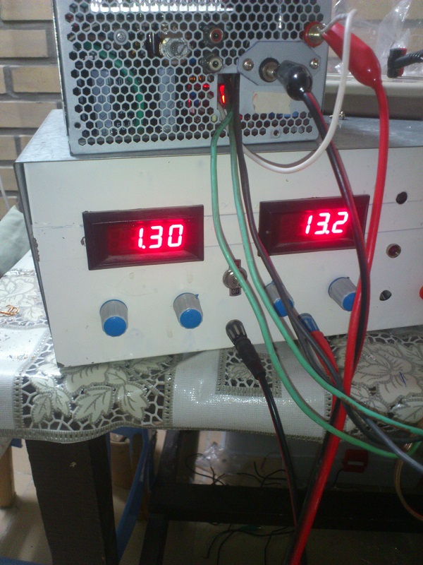
i make this for my car .when no load,no sound:
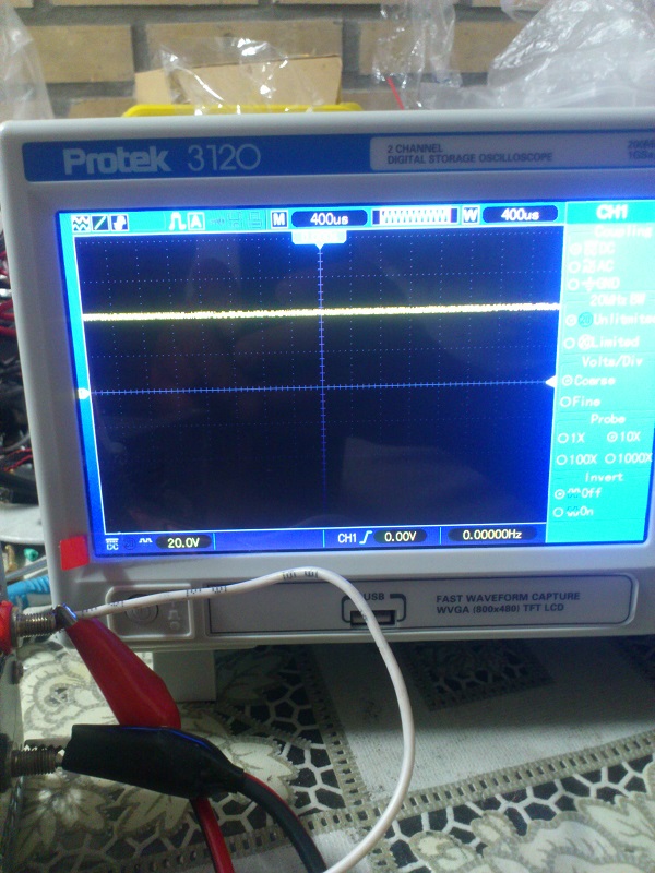
this is -40v supply:
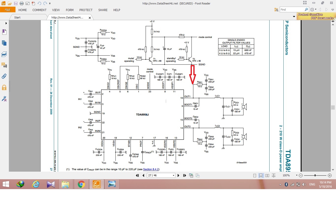
i make this schematic: and the next pic is this point fletcher to gnd
this is +40v supply:
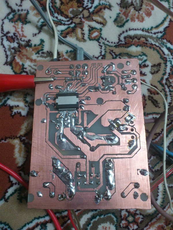
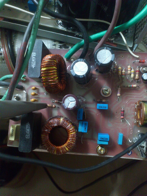
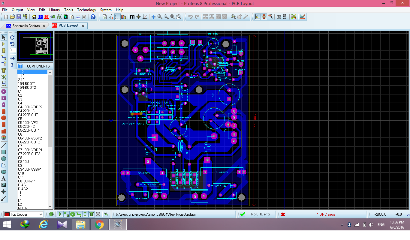
this pcb:
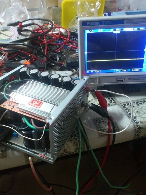
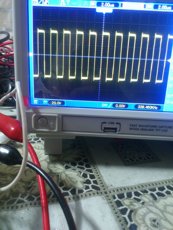
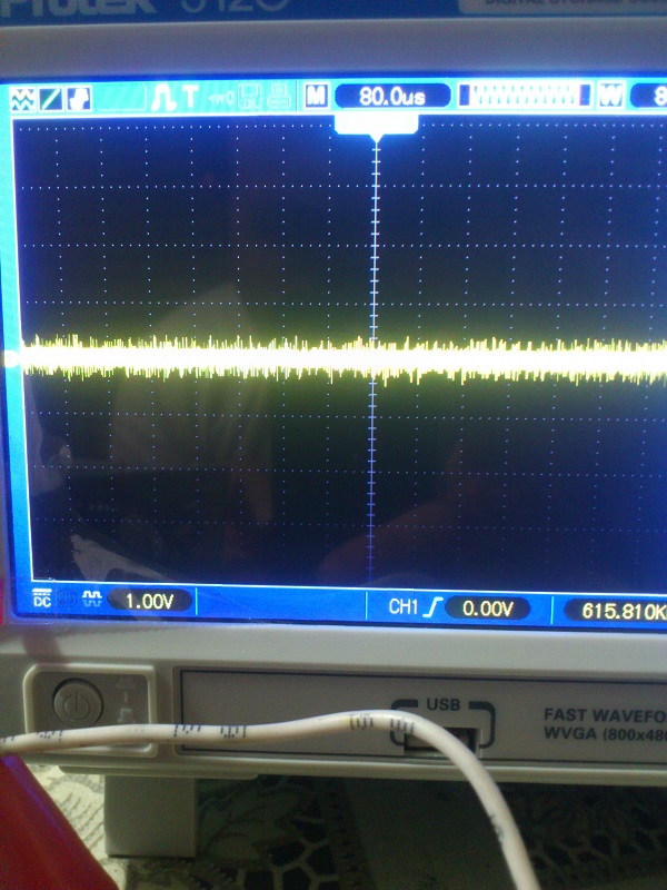
this is output ,without input signal:
even i split the coil from pcb ,again ic be warm,and it pulls current but a few less than before .
Last edited:
The schematic you showed is for a different package. You took 30 minutes of my time for nothing. :-(
On a single layer PCB, with through hole parts you have to be an expert to make a usable layout for ClassD amp. Use a GND plane at least!
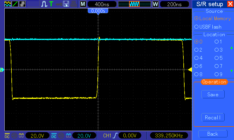
On the output your measurement is absolutely useless, nothing can be seen from the signal. On the switching node you show 11 identical periods, without visible details of transition. You should show only 1 period, but with full details. (Rise and fall separated with 100ns/div max.)
Power supply must be measured directly on IC pins, triggered correctly, and again: 100 ns/div max, otherwise it's also useless.
What is the core? T106-2 is not yellow.
MLCC is good for decoupling power pins, but absolutely not for coupling audio signal. TH foil capacitors should come here!
On a single layer PCB, with through hole parts you have to be an expert to make a usable layout for ClassD amp. Use a GND plane at least!
On the output your measurement is absolutely useless, nothing can be seen from the signal. On the switching node you show 11 identical periods, without visible details of transition. You should show only 1 period, but with full details. (Rise and fall separated with 100ns/div max.)
Power supply must be measured directly on IC pins, triggered correctly, and again: 100 ns/div max, otherwise it's also useless.
What is the core? T106-2 is not yellow.
MLCC is good for decoupling power pins, but absolutely not for coupling audio signal. TH foil capacitors should come here!
Last edited:
dear pafi , thank you very much and sorry about take your time.
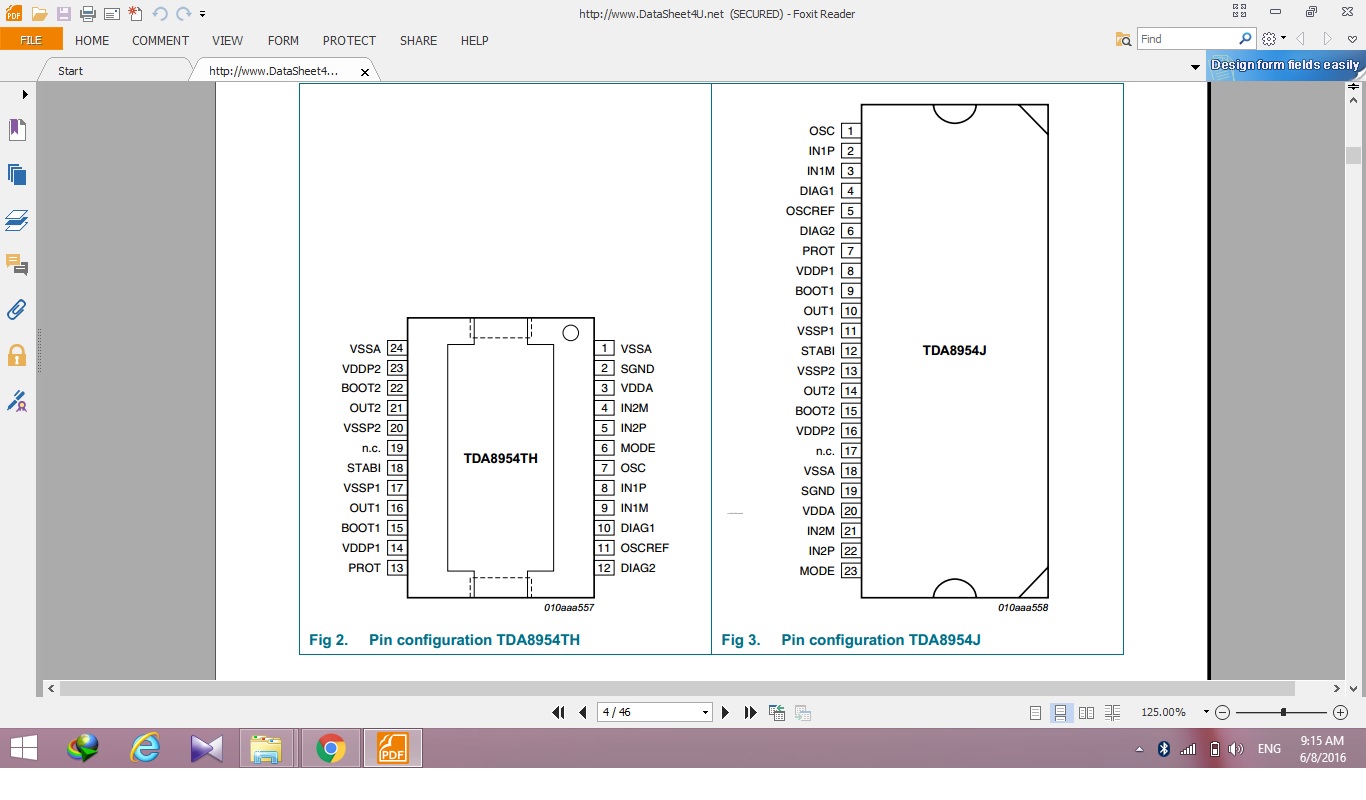
at the datasheet just there is this schematic ,but pin layout for smd package
there is and it's different.
sorry ,i forget attach it.
you say "Use a GND plane at least!" ,this pcb have good sound quality.there isn't noise on output.so, is there other reason for gnd plan?
the core is T106-6. I can't reach T106-2.
a bout MLCC capacitors ,so i seen these capacitors at very audio systems to coupling audio signal?
a bout warming IC ,maybe Ic is fake?! i bought it 5$ and it's from china.
Last edited:
Shahpoori,
I can see the pinouts, but I don't have time to create the real schematic, and I cant watch PCB and pinout list and schematic the same time on mobile phone, so I will not check the design in details.
The switching node waveform is now detailed satisfying, and not bad, but contradictionary, in a correct design it should be much faster. If you could show the output waveform with the same quality, the ripple current of inductor could have been calculated. Probably it's very low.
Staying ontopic: the output coil is totally different from the advised. AL=116. I don't think this deviation alone can be the reason of the heat, what is more if you change it to the correct one you may experience much worse operation, because at the correct amount of ripple current the bad layout will show its real face. Now because of the very low current the high parasitic inductances of your layout doesnt do much.
The IC can be also wrong, but as long as everything else are uncertain, different from optimal, I cant tell anything about it.
"High quality" is extremely subjective, I don't know what it means for you. Low noise is only 1 factor, and doesn't mean your circuit, your layout is good.
MLCC is acceptable for audio only if it is overscaled. Higher capacity, high voltage, big case, and good material.
Oops, the Al specification was misleading, it was given in uH/100 turn, so it is only 11.6 given in the usual way.
i test the circuit no load; no filter; no RC-snubber network connected; and again Ic consume about 10W .
according to datasheet in that condition it should be 75ma max.
and with 4 ohm load without sound should be about 6w .
may be IC is damaged? or it isn't original?
according to datasheet in that condition it should be 75ma max.
and with 4 ohm load without sound should be about 6w .
may be IC is damaged? or it isn't original?
Hi, I am also working on the TDA8954 now. The heat is a big problem that I did not expected. After some test I find it is resonable that is the high frequency going to be. Otherwise they will only stay in the circuit even it is not a big problem. I am going to put two 10W resistors between the 0.1u Cap and the GND (BTL circuit that I use is only one 0.47u across the output). The higher the voltage we use the higher the Watt will need to make. Does anybody has more experience about this? There is not any information about the real circuit I can find. May be I can only make my own things.
From the data sheet:
"14.5 Heatsink requirements
An external heatsink must be connected to the TDA8954."
What is the voltage on your supply rails?
"14.5 Heatsink requirements
An external heatsink must be connected to the TDA8954."
What is the voltage on your supply rails?
Yes, a big heaksink is must. If I follow the circuit of the spec., the chip will down over +-18V. The inductor will be also very hot when it works on this low voltage. I think it is better to use suitable voltage for the target system. +-41V can give max. power but it will give a great heat even you use the low power.
Even at really good efficiencies some heat sinking will be required.
100w at 90% efficiency gives 11 watts of heat. It has to go somewhere. The TDA8954 quotes 93% efficiency but that will be at max power.
At lower powers the efficiency can be much lower.
Also remember that the quality of the inductors will also be a factor as if they are running hot, they may be the wrong type or the wrong value.
Sent from my iPhone using Tapatalk
- Home
- Amplifiers
- Class D
- TDA8954 output filter