I'm sure one of the series, including TDA8920BTH, TDA8950TH and the newest one TDA8954TH can be used as a replacement.
TDA8920BTH can be used as a true drop-in replacement. However, pay attention that the TDA8950TH has both pin 10 & 12 unconnected, whereas TDA8954TH chip has two different functions on pin 10 & 12, used for Diagnostics instead of VDD & VSS as in TDA8920/24TH.
TDA8920BTH can be used as a true drop-in replacement. However, pay attention that the TDA8950TH has both pin 10 & 12 unconnected, whereas TDA8954TH chip has two different functions on pin 10 & 12, used for Diagnostics instead of VDD & VSS as in TDA8920/24TH.
Thanks for the reply norture.
Not to doubt you, but how are we sure TDA8920BTH is a drop in replacement for TDA8924TH? I can't seem to find any reference to this.
If TDA8920BTH really is a pin for pin replacement, then TDA8950TH must be as well since the NXP site says they are both compatible.
I guess I'll just get a couple TDA8950TH and see. They're only $5.61 each, so I'll add them to my next avnet order.
Well, it seems this amp still has some demons. 
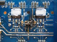
I first purchased it knowing it had two channels not working and hoped it would be a simple fix. When I opened it up to check it out the first time I noticed a blown SMD cap by the rear channel IC. It was a 220nF ceramic that went from the negative rail to ground. It did some damage to the board and a trace that ran under the cap which I fixed. I replaced the cap with two parallel 100V 100nF caps I pulled off another board. After the repairs the rear channel still didn't work so I replaced both TDA8924 with the 8950's.
Today I was doing some cruising in my car and the amp was playing perfectly for a couple hours. I started to smell the smell of death and the amp began to cut in and out so I quickly reached behind my seat and yanked the power connector off. I tried to pick the amp up but the whole thing was insanely hot.
When I got home I connected it to a 12V supply and powered it up and immediately heard a "pop". After opening it up I noticed that the 220nF cap on the positive rail had now vaporized just like the negative rail had originally. I powered it up again without any further fireworks and tested the rear channels.... they still work!
Anyway, to get to the point; why would these 220nf ceramic decoupling caps be shorting like this and why ony on the rear channels? Also, another thing I noticed with this amp is there are two 63V 1000uF caps per IC across the rails, not one going from each rail to ground (+/-25.8V rails). This doesn't seem right since the outputs are single ended.
The more I look at the layout of this board the more it looks like it was designed to be used in bridge mode exclusively, except it wasn't. Either that or the designers just didn't care much for the datasheet.
The datasheet shows 100nF going across VDDP and VSSP for each channel, and also 100nF from each supply rail to ground, for a total of 6 100nF caps. On this amp board there is only 1 cap of unknown value across VDDP and VSSP. The 220nF caps mentioned earlier are relatively far away from the IC leads.
The datasheet shows 100nF going across VDDP and VSSP for each channel, and also 100nF from each supply rail to ground, for a total of 6 100nF caps. On this amp board there is only 1 cap of unknown value across VDDP and VSSP. The 220nF caps mentioned earlier are relatively far away from the IC leads.
...why would these 220nf ceramic decoupling caps be shorting like this and why ony on the rear channels? Also, another thing I noticed with this amp is there are two 63V 1000uF caps per IC across the rails, not one going from each rail to ground (+/-25.8V rails). This doesn't seem right since the outputs are single ended.
I smell something fishy about your board. Do you have the schematic? I've never seen caps being put across the rails like that. And you seem to have severe ripple/oscillation problem.
I smell something fishy about your board. Do you have the schematic? I've never seen caps being put across the rails like that. And you seem to have severe ripple/oscillation problem.
I've tried looking for a schematic for it (Blaupunkt THA-475), but no luck.
It does seems like what you drescribe and I can only assume it's related to the poor decoupling scheme chosen by the designers. I don't understand how a company like Blaupunkt could overlook such a thing though.
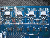
I also have a 5-channel version THA555 that is brand new. Taking the bottom off it looks like a similar layout to the other one, just with 4x IC's instead of two. Again the 63V 1000uF local decoupling caps by the IC's look to be all in parallel across the rails.
I can easily add some proper 100nF decoupling by the IC power leads on this wonky board, but I don't see an easy way to reconfigure those 1000uF caps.
EDIT: Oh, one thing I overlooked and forgot to mention. There are 4x 1000uF 35V caps across the rails (two each rail), but they are in a CLC configuration by the supply transformer a few inches away from the IC's.
Attachments
Haha.... so much for that "brand new" Blaupunkt THA555.
I put the THA555 in my car and as soon as I powered it up I heard "bzzzzzzzzz..... pop". I knew exactly what happened.
So I take the thing apart and sure enough two of those 220nF ceramics went up in smoke. The IC they're near survived though.
If it weren't for the fact I purchased the other amp with one of these caps already blown I would probably blame these catastrophes on my wiring. I mean the wiring itself is fine, but I have two small switching supplies in my setup, one for +/-15V line level circuits and one +5V for USB power and to power a bluetooth receiver. It's possible the noise from one of these is getting to the amp inputs, but there should be sufficient RF filtering on the inputs if it were designed properly. Any noise there might be never bothered the small Tripath amp I had hooked up before though.
I don't know. I'm going to remove all of those explosive 220nF caps and put the proper decoupling scheme near each IC power lead and see what happens. I'm also going to put ferrite chip inductors right at the audio inputs on the IC's.
Attachments
Single capacitor directly from +Vdd to -Vss give lower supply impedance than series capacitors split at ground. Half bridge class D requires both, the ones from +Vdd to -Vss for handling the switching ripple, and the ones split at ground to keep a center voltage.
High voltage & high value (high "density") ceramic capacitors 1206 or bigger are easily damaged by board flexing during or after manufacturing. Micro-cracks in the fine dielectric layers end up allowing the cap to short itself and explode. Too much solder or lack of flex-friendly PCB pad design make caps more vulnerable. I suggest replacing all ceramic caps of that type in that zone of the PCB, preferably solder new ones with hot air and tweezers, use little solder, rubbing the terminations of these caps with soldering iron will make them fail later, no force is allowed. Heating too much or for too long can cause early failure.
High voltage & high value (high "density") ceramic capacitors 1206 or bigger are easily damaged by board flexing during or after manufacturing. Micro-cracks in the fine dielectric layers end up allowing the cap to short itself and explode. Too much solder or lack of flex-friendly PCB pad design make caps more vulnerable. I suggest replacing all ceramic caps of that type in that zone of the PCB, preferably solder new ones with hot air and tweezers, use little solder, rubbing the terminations of these caps with soldering iron will make them fail later, no force is allowed. Heating too much or for too long can cause early failure.
Last edited:
High voltage & high value (high "density") ceramic capacitors 1206 or bigger are easily damaged by board flexing during or after manufacturing. Micro-cracks in the fine dielectric layers end up allowing the cap to short itself and explode. Too much solder or lack of flex-friendly PCB pad design make caps more vulnerable. I suggest replacing all ceramic caps of that type in that zone of the PCB, preferably solder new ones with hot air and tweezers, use little solder, rubbing the terminations of these caps with soldering iron will make them fail later, no force is allowed. Heating too much or for too long can cause early failure.
Thanks for the tips Eva. I've just ordered some new 220nF 100V 1210 X7R capacitors and I'm going to replace all of them. I'll use solder paste and a hot air station like you suggested.
I have a different/new problem with the board I put the TDA8950 on. I think it's overheating due to oscillation; the output coils get extremely hot. I just noticed in the datasheets that the 8924 has 4R7 in series with 560pF from each output to ground. The 8950 datasheet shows 10R going to two 220pF caps, one connected to VDDP and one to VSSP. I wonder if this is the cause.
Eva hit the nail on the head about the cermaic caps being damaged and shorting out. The caps are right next to screw holes used for clamping the board to the heatsink. It's interesting that none of the caps rotated 90 degrees have shorted.
I also think I jumped the gun with the TDA8950 as replacements. I've been trying to figure out why the output inductors are overheating. I don't own a scope but I checked the outputs with a frequency counter and the carrier is at 180kHz; the other 5-channel amps outputs are all at 375kHz.
After looking through the datasheets again it seems the 8950 divides the external clock signal but the 8924 doesn't. So I guess I need to either scrap the idea of using the 8950 or double the external clock frequency, which I'm not capable of figuring out.
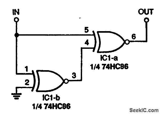
The clock on these amplifiers in generared by a HEF4060B, but without a schematic I'm lost on how to adjust the frequency. I'm not sure that would be smart anyway since it looks like the clock is also going to the SG2525 for the power supply.
I'm just going to find a 74HC86 and try the circuit I posted above between the output of the HEF4060B and the Osc inputs of the TDA8950. Nothing much to lose in trying.
I'm just going to find a 74HC86 and try the circuit I posted above between the output of the HEF4060B and the Osc inputs of the TDA8950. Nothing much to lose in trying.
Alright, so I finally just decided to get new TDA8924. After weeks of waiting for them to arrive, I got them installed on the board today.
Everything works and it plays music just fine, but the output inductors are overheating like they did with the TDA8950. Even at idle with no signal they're reaching 70C!!!
Any last words of advice from anyone before I just toss this thing in the trash?
Everything works and it plays music just fine, but the output inductors are overheating like they did with the TDA8950. Even at idle with no signal they're reaching 70C!!!
Any last words of advice from anyone before I just toss this thing in the trash?
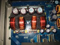
As a last resort here, I swapped out the original shielded bobbin inductors for toroids and it seems to have fixed the problem. The amp has been playing music for over an hour and the toroids are only around 35C.
Idle current on the input to the amp dropped from 1.8A to 1.2A.
Is it possible for bobbin inductors to go bad?
It's kind of disappointing that changing the inductors fixed the overheating. I had the TDA8950 working perfectly; synced with a precision 0.75MHz crystal oscillator.
Idle current on the input to the amp dropped from 1.8A to 1.2A.
Is it possible for bobbin inductors to go bad?
It's kind of disappointing that changing the inductors fixed the overheating. I had the TDA8950 working perfectly; synced with a precision 0.75MHz crystal oscillator.
Attachments
- Status
- This old topic is closed. If you want to reopen this topic, contact a moderator using the "Report Post" button.
- Home
- Amplifiers
- Class D
- TDA8924TH compatible replacements?