Hi Everyone,
First post here, hopefully the first of many since I'm planning to do lots of Audio projects from now on.
So, I searched everywhere for answers to my questions but couldn't find any straight explanation, hope that the experts around here can shed me some lights on this.
I bought two TDA7492 Class D amplifiers (Link), they produce 50W x 2 at 8ohm or 100W x 1 at 4ohm.
Here's what I want to do:
Connect each amp on MONO to each speaker (one with Left audio input, the other with Right), making it a 4ohm Stereo System.
Regarding the Audio input I already figured it out (pretty basic actually...), what I can't find anywhere is how to make each Amp Mono Bridged. I read somewhere that I would have to do a PBTL (parallel bridge tied load?) because the amplifier is already BTL for both channels, but I have no idea of what that means in terms of wiring.
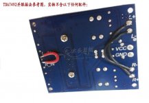
I found on a different ebay listing a picture that apparently shows how to do it, however I don't read chinese so I can't be sure, eitherway I'm pasting the picture here just in case it is the correct way of doing it.
Please help this newbie, I spent hours and hours looking for this an couldn't find it, and I don't want to risk testing because I'll probably end up frying the IC 😀
Many Thanks in advance.
First post here, hopefully the first of many since I'm planning to do lots of Audio projects from now on.
So, I searched everywhere for answers to my questions but couldn't find any straight explanation, hope that the experts around here can shed me some lights on this.
I bought two TDA7492 Class D amplifiers (Link), they produce 50W x 2 at 8ohm or 100W x 1 at 4ohm.
Here's what I want to do:
Connect each amp on MONO to each speaker (one with Left audio input, the other with Right), making it a 4ohm Stereo System.
Regarding the Audio input I already figured it out (pretty basic actually...), what I can't find anywhere is how to make each Amp Mono Bridged. I read somewhere that I would have to do a PBTL (parallel bridge tied load?) because the amplifier is already BTL for both channels, but I have no idea of what that means in terms of wiring.
I found on a different ebay listing a picture that apparently shows how to do it, however I don't read chinese so I can't be sure, eitherway I'm pasting the picture here just in case it is the correct way of doing it.
Please help this newbie, I spent hours and hours looking for this an couldn't find it, and I don't want to risk testing because I'll probably end up frying the IC 😀
Many Thanks in advance.
Attachments
I have that module but have not used it yet. However mine has a low voltage Electrolytic smoothing cap (25V). Check yours before you power up.
Thanks for pointing that, so basically that means that if I make a simple mistake when wiring the speakers (inverted polarity for example) I will trash the IC instantly?
Sorry, just starting in electronics so many basic concepts are still unfamiliar to me.
Thanks, will keep digging anywhere I remember to see if I find an answer to this.
Sorry, just starting in electronics so many basic concepts are still unfamiliar to me.
Thanks, will keep digging anywhere I remember to see if I find an answer to this.
Connect the R+ to the L+ and the R- to the L- to parallel the outputs. Also the data sheet recommends using the internal oscillator for the first IC then use the synclk connection to clock any additional ICs from the first IC.
Extract from TDA7492 data sheet:-
6.4
Applications information
Internal and external clocks
The clock of the class-D amplifier can be generated internally or can be driven by an external source. If two or more class-D amplifiers are used in the same system, it is recommended that all devices operate at the same clock frequency. This can be implemented by using one TDA7492 as master clock, while the other devices are in slave mode, that is, externally clocked. The clock interconnect is via pin SYNCLK of each device. As explained below, SYNCLK is an output in master mode and an input in slave mode.
6.4.1
Master mode (internal clock)
Using the internal oscillator, the output switching frequency, f SW , is controlled by the resistor, R OSC , connected to pin ROSC:
f SW = 10 6 / ((R OSC * 16 + 182) * 4) kHz
where R OSC is in kΩ.
In master mode, pin SYNCLK is used as a clock output pin whose frequency is:
f SYNCLK = 2 * f SW
For master mode to operate correctly, then resistor R OSC must be less than 60 kΩ as given below in Table 8.
6.4.2
Slave mode (external clock)
In order to accept an external clock input the pin ROSC must be left open, that is, floating. This forces pin SYNCLK to be internally configured as an input as given in Table 8.
The output switching frequency of the slave devices is:
f SW = f SYNCLK / 2
Table 8.
How to set up SYNCLK
Mode ----- ROSC -------------------- SYNCLK
Master --- R OSC < 60 kΩ -------- Output
Slave - Floating (not connected) - Input
Hope this helps.
- Status
- Not open for further replies.