Hi all,
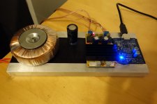
I've built a 100W amplifier which is working very well. The sound is sublime!
But, I've noticed the inductor heat is HOT. I mean, I can't keep my finger on the top of it. This is with the amp on (standby not engaged) but with no input signal, thus it seems to be the high switching frequency of the Tdk causing the heat?
Input is 25V AC so about 35V DC. Perhaps a bit too high, but within spec.
The board I chose for the nice features, good caps and 220uF inductors. TDA7498 100W+100W HIFI Class D digital amplifier Board 12v 24v car AMP Audio | eBay
Cheers
Andrew
Attachments
This is a known thing with switching designs, especially if the inductor is speced to a price or size requirement.
The biggest physical size for the desired inductor with minimum DC resistance is a general rule, all helps keep the temperature down. Generally these designs are best with 4 2oz copper layers, thermal vias and heat sinking for the hot passives as you have. The problem is the inductors need to be near the switching circuitry (often the controller its self) creating localised hot spots. Thermal management is a big part of the design cycle.
The biggest physical size for the desired inductor with minimum DC resistance is a general rule, all helps keep the temperature down. Generally these designs are best with 4 2oz copper layers, thermal vias and heat sinking for the hot passives as you have. The problem is the inductors need to be near the switching circuitry (often the controller its self) creating localised hot spots. Thermal management is a big part of the design cycle.
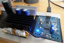
The inductors might not be sized properly for that voltage swing (switching, not audio)
They look like the size used for TPA3116/8 type amps (24V supply)
What happens if you reduce the supply? Do the inductors run cooler?
You could also attach a heat sink to them or replace them with larger inductors.(might be ugly but reduce thermal losses)
They look like the size used for TPA3116/8 type amps (24V supply)
What happens if you reduce the supply? Do the inductors run cooler?
You could also attach a heat sink to them or replace them with larger inductors.(might be ugly but reduce thermal losses)
On my first class d amp I just bought in 22uH power supply inductor.
It was running at 120 degrees C !
Someone suggested a T106-2 core with about 20 turns on it and that worked great and barely got warm.
It was running at 120 degrees C !
Someone suggested a T106-2 core with about 20 turns on it and that worked great and barely got warm.
I've not tried it with a 24V supply, highest I can go to is 20V if I use DC with the equipment I have. I'm pretty sure it's less heat. The board requires 36V for full 100W output.
I've now heatsinked them as they are burning hot! I mean, there's more heat from the inductors than the main IC at lower volume!
The heatsink is now at 80c!
Next I'm wondering if the input cap's on the 7498 are necessary. The input source is a USB dac which doesn't need them (I've bypassed the two silver electrolyics on the blue board).
Attachments
Last edited:
Current consumption at 20V was really minimal, 0.12v at lower volume. No doubt it's much higher at 36V but I haven't checked it. It appears the switching frequency voltage is linked to supply voltage not input voltage (I always assumed it to be the latter)
Andrew
Andrew
Three things can cause inductor to run hot.
1/ Wire is too resistive.
2/ Wrong core material.
3/ Heat conducted from other components into inductor.
1/ Wire is too resistive.
2/ Wrong core material.
3/ Heat conducted from other components into inductor.
Can rule out (3). They are doing a good job heating everything else up though.
Looking at the schematic, if there was less resistance (4, 2) wouldn't it just pass more current through the mosfet switch and thus result in more current being lost in the 7492?
http://g01.a.alicdn.com/kf/HTB1AV0i...ping-Assembled-TDA7498-A1-amplifier-board.jpg
Input DC is 37.4V (rather high!)
Looking at the schematic, if there was less resistance (4, 2) wouldn't it just pass more current through the mosfet switch and thus result in more current being lost in the 7492?
http://g01.a.alicdn.com/kf/HTB1AV0i...ping-Assembled-TDA7498-A1-amplifier-board.jpg
Input DC is 37.4V (rather high!)
Last edited:
T106-2 is good indeed, but 20 turns are not enough; for 22 uH 40 turns are needed.
And there are many other solutions.
And there are many other solutions.
Current consumption at 20V was really minimal, 0.12v at lower volume
I guess you mean 0.12A, right? It is not minimal but quite high. Mine operates with 48 mA quiescent current. Those inductors must be cheap crap.
Looking at the schematic, if there was less resistance (4, 2) wouldn't it just pass more current through the mosfet switch and thus result in more current being lost in the 7492
Which resistance? I guess you mean load. But no connection between idle loss and load resistance.
But wait a minute! What are we talking about? TDA7492 or 7498? There is 7492 in the title of topic, but you linked 7498.
Next I'm wondering if the input cap's on the 7498 are necessary.
Yes, they are.
In my limited experience, ferrite cored inductors fitted to el-cheapo amp boards are extremely lossy (aka cheapo). Hence run hot even with zero signal. To get the amp to run cool, seek out a Coilcraft inductor of the same value and size. You'll probably pay close to the original price of the board for a set of 4.
Good god so many errors. I got off the plane earlier and I'm clearly a bit tired.
Chip -> 7498
Inductors -> 22uF (220 on top - doh)
20V is 0.12A quins.
I've just noticed the input cap's are 1uF, below the 2.2uF recommended, so they're out.
The inductors are 22uF 3A 12x12x7mm (common). I've just smashed one taking the heatsink off and the wire is really thin. Will go to 10A I think.
Andrew
Oddly there is a 20ohm resistor in series with the input capacitor.
Apologies for the writing mistakes. I'm taking myself to bed!
Apologies for the writing mistakes. I'm taking myself to bed!
- Status
- Not open for further replies.
- Home
- Amplifiers
- Class D
- TDA7492 Inductor Heat