hey, i have that kind of amplifier where is the logitech x-530 set that has its own amplifier fluttering and now i need some help because the subfoower has vocals and not bass.
Attachments
You have managed to put all in a single sentence, which in itself is impressive, but I do not understand the problem or question.
Could you please try again, eventually with a bit more elaborate explanation?
Could you please try again, eventually with a bit more elaborate explanation?
Last edited:
The problem is that the subwoofer makes a human singing voice. I have connecting two speakers and one subwoofer.
OK:
You have a system with two satellite speakers (full frequency range except deep bass) and a sub-woofer for deep bass tones. Correct?
Your two satellite speakers work correctly?
Your sub-woofer does not work well as it makes a rather high pitch tone sounding like a human voice. Correct?
Is that with a signal at the input of the sub-woofer amplifier? or, without a signal at the input of the sub-woofer amplifier?
The TDA7377, what is that used for? as a sub-woofer amplifier?
Hi Ter082
Hmm... its not really what FF means.
but step by step.
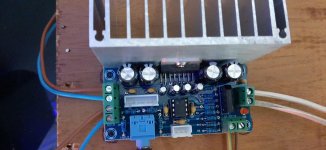
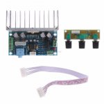
this is your board I guess:
TDA7377 2.1 sound channel 20W*2+30W Bass Hifi power amplifier board with tone board volume adjustment subwoofer Audio amplifier-in Amplifier from Consumer Electronics on AliExpress
my comment first to the power supply : at one pic at aliexpress you see the recommended input Voltage 12V AC - thats ok. the chip must not be driven to its max. supply voltage.
I can´t make the pic from the schematic cleaner/bigger....
A sub chassis without a cross over /filter for higher frequencies and an unknown filter from a board can make some not "needed" vocals.
Did you try all the knobs for adjustments- What happened??
chris
Hmm... its not really what FF means.
but step by step.
this is your board I guess:
TDA7377 2.1 sound channel 20W*2+30W Bass Hifi power amplifier board with tone board volume adjustment subwoofer Audio amplifier-in Amplifier from Consumer Electronics on AliExpress
my comment first to the power supply : at one pic at aliexpress you see the recommended input Voltage 12V AC - thats ok. the chip must not be driven to its max. supply voltage.
I can´t make the pic from the schematic cleaner/bigger....
A sub chassis without a cross over /filter for higher frequencies and an unknown filter from a board can make some not "needed" vocals.
Did you try all the knobs for adjustments- What happened??
chris
 Well spotted Chris. We are approaching the core of the problem. The second OP-AMP circuit (from the left) should form a band-pass filter. Out of the four (SE) TDA7377 channels two are used in SE-mode for full-tone stereo and two are used in BTL-mode for the sub-channel.
20Wx2 + 30W -> very optimistic.
20Wx2 + 30W -> very optimistic. 😛😛
Yes ...at the datasheet its shown as figure 3 - or lets say the 3rd configuration what is possible with this chip. 2 channels SE L+R and the subwoofer channels is bridged.
my first guestimation is that the second board - which is used for volume , treble and bass is not really working and /or the opamps on the "main" board are not correct set to "build" a bandbass...
There is no schematic for the small board with the potentiometers. A guess: the "master volume" potentiometer regulates the general signal level to the board. "High pitch" could mean the level for the two full-range speakers while "bass" rather obviously is the level to the sub-channel.
The bandpass filter is shown to be a fixed filter. I doubt that there is bass and treble regulation as the small board only has few and passive components.
The bandpass filter is shown to be a fixed filter. I doubt that there is bass and treble regulation as the small board only has few and passive components.
There is no schematic for the small board with the potentiometers. A guess: the "master volume" potentiometer regulates the general signal level to the board. "High pitch" could mean the level for the two full-range speakers while "bass" rather obviously is the level to the sub-channel.
The bandpass filter is shown to be a fixed filter. I doubt that there is bass and treble regulation as the small board only has few and passive components.
Also typical of those cheap amps, which are generally used with cheap speakers, the bass crossover is likely at 200 or 300hz. So yes you will hear some parts of voices from the woofer as normal.
They work nice but I thing that r9 and r10 metal firm resistor are wrong. They are 1 kohm and I thing I change they to 1.50 kohm. Sorry bad english
Hi Tero, good to hear from you.
We have the problem that we do not know exactly how the small board with the potentiometers work. We would like you to do some small tests:
1) Amplifier power OFF.
2) Connect all three speakers (two stereo speakers and one bass speaker) to the amplifier board and prepare some music to be played, music without voices but good level bass and mid-tone. Turn the "master volume" (potentiometer to the left) fully down (counter clock-wise) and the "high pitch" (potentiometer in the middle) and "bass" (potentiometer to the right) fully up (clock-wise).
3) Turn the amplifier power ON and turn the "master volume" up (clock-wise) until you have a reasonable sound-level for listening.
4) Turn the amplifier power OFF and following disconnect the two stereo speakers such that only the bass speaker is connected to the amplifier board.
5) Turn the amplifier power ON. Try first to turn the "bass" potentiometer (the one to the right) fully counter clock-wise and then back to fully clock-wise. Does this cause the sound in the bass speaker to fully disappear or does it just change the amount of bass? Then, turn the "high pitch" potentiometer (the one in the middle) fully counter clock-wise and then back to fully clock-wise. Does this cause the sound in the bass speaker to change the amount of bass or has it no influence on the sound in the bass speaker?
6) Turn the amplifier power OFF, then disconnect the bass speaker and re-connect the two stereo speakers to the amplifier board.
7) Turn the amplifier power ON. Try first to turn the "bass" potentiometer (the one to the right) fully counter clock-wise and then back to fully clock-wise. Does this cause the sound in the stereo speakers to change the amount of bass or has it no effect on the sound in the stereo speakers? Then, turn the "high pitch" potentiometer (the one in the middle) fully counter clock-wise and then back to fully clock-wise. This should change the amount of treble in the stereo speakers, correct?
8) Turn the amplifier power OFF, then re-connect the bass speaker to the amplifier board.
That was the first test. I will continue in a following posting.
Last edited:
The small board with the three potentiometers may be constructed in one of three ways:
a) The "master volume" regulates the signal level to both the stereo speakers and bass speaker while the "high pitch" and "bass" potentiometers regulate treble and bass to both the stereo speakers and the bass speaker. This is the least good design option.
b) The "master volume" regulates the signal level to both the stereo speakers and the bass speaker while the "high pitch" potentiometer regulates the sound in the stereo speakers only. The "bass" potentiometer regulates the amount of bass in the stereo speakers only or the sound level of the bass speaker only. This is a much better design option.
c) The "master volume" regulates the signal level to both the stereo speakers and the bass speaker while the "high pitch" potentiometer regulates the sound level in the stereo speakers only. The "bass" potentiometer regulates the sound level of the bass speaker only. This is, in my view, the best design option.
The tests above should tell us which of the three designs ( "a)", "b)" or "c)") is used.
If we can improve the design, I do not know yet but at least we should understand why it works the way you observe.
You cannot avoid human voices from being reproduced by the bass speaker also. Male voices have a frequency range down to around 200Hz while female voices start a bit higher. 200Hz-300Hz is a part of what your bass speaker is supposed to reproduce. Further, the bandpass filter for the sub-amplifier is rather simple and does not cut higher frequencies off with a steep slope.
Last edited:
hey, i guess that small plate is the worst design option, option A
Many thanks for testing. Chris was right.
When you first shape the sound balance to fit the two stereo speakers (not too much bass) and then try to extract the remaining bass to a sub-channel, it is not much deep bass that arrives at the bass speaker.
It is a simple system which you cannot expect miracles from.
You can use it as it is or take the signal for the sub-channel directly after the "master volume" potentiometer. That should allow more bass.
As explained before, you cannot expect voices to disappear completely from the bass speaker.
Last edited:
Could you tell me how to take that subchannel signal right after the "master volume" potentiometer and where to hook it up
Could you tell me how to take that subchannel signal right after the "master volume" potentiometer and where to hook it up
I will try. Could you please give me the value written on the "master volume" potentiometer? It should something like "50K" or "22K".
Thanks. Then try to connect a 22K resistor to each of the "master volume" potentiometer middle-terminals. The free ends of the two 22K resistors you connect together (this forms a resistive mono-summing of the two channels). The circuit schematic Chris found shows that the line connected to pin 6 of the small connector is for the sub-channel. That line has to be interrupted, eventually on the small board, and connected to the point where the two 22K resistors are connected together.
Last edited:
- Home
- Amplifiers
- Chip Amps
- Tda7377 2.1