Hello everyone,
I'm thinking about making a PCB for a design with TDA7297, I know that with other TDAs, and I think this one is not an exception you have to connect input ground near the TDA at the same PCB, I don't know if I can connect the input ground at the power supply star ground point (which seems better), I've tried to simulate both situations in breadboards and I've only obtained good results when the input ground is connected near the TDA7297 IC (the problem is the very poor impedance characteristics of breadboard conductors). Can anyone help me solving this problem?
I've never made a PCB before, I've only mounted several low power audio opamps (always on breadboards) and I'm afraid of making a PCB that doesn't work like expected.
PCB layouts (Power Supply, TDA7297/TDA2822M and respective voltage regulators) attached to this post.
Thank you very much for your atention,
Best regards,
Daniel Almeida
Attachments
You would always want the input ground conductor to stay very close to the input signal conductor, anyway. Otherwise you will be creating "enclosed loop area" which will make an antenna.
You should tightly twist the input signal and input ground wires together, all the way from the input jack to the pcb. Input jack must also be isolated from chassis, so input ground does not get connected to chassis, accidentally. Even better: Use shielded twisted pair, with input signal and input ground on twisted pair, and shield connected to chassis, at one end only, and connected to nothing on the other end.
On the PCB, keep input and input ground traces very close together, with minimal gap between them, everywhere. Pour copper for input ground so that it surrounds all input signal traces and related components.
Input ground on PCB should have separate connection back to star ground, i.e. not mixed with power ground.
Last edited:
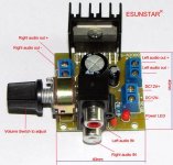
Just bought an amp using the 7297
Danny,
It's REALLY good. You won't regret any effort you put into using it.
I started a thread on the class D amp section http://www.diyaudio.com/forums/class-d/231988-what-heck-its-less-than-lunch.html about this amp pictured below.
Good luck!
Mark
Danny,
It's REALLY good. You won't regret any effort you put into using it.
I started a thread on the class D amp section http://www.diyaudio.com/forums/class-d/231988-what-heck-its-less-than-lunch.html about this amp pictured below.
Good luck!
Mark
Attachments
- Status
- Not open for further replies.