Hello everyone,
I'm designing a PCB layout for a TDA7297 application, the problem is that I want to use it with a regulator (at the same board), a TDA2822M application (with a 7805 regulator) for headphones amplifier and a Vumeter ( to sense the input amplitude) based on LM3915.
I'm thinking in connecting the input ground, TDA7297 ground connections, TDA2822M ground connections and LM3915 all to the power supply ground near the large reservoir capacitors (it's my first PCB layout), but when I breadboarded this solution this doesn't work, I've to put the input potenciometers, TDA7297 and TDA2822M grounds (and respective voltage regulators) in the same breadboard, with input ground also connected to this bredboard, and the power supply is in another one, otherwise I've got floating input, I don't understand why power supply star grounding causes input floating, this topology doesn't help?
Atached Eagle layouts for TDA7297, TDA2822M, LM3915 and single power supply (bridge rectifier doesn't appear but the package is KBL).
The input pots ground, headphones ground, TDA7297 board ground, TDA2822M board ground, LM3915 board ground and input ground could be connected to the power supply star ground point in the power supply PCB?
Thank you very much for your atention,
Best Regards,
Daniel Almeida
Attachments
Last edited:
TDA7297 Supply Design
Hello everyone,
In this post I send attached the schematic of the power supply and another power supply design, I don't understand what's wrong with the first design, but I've made another one (bridge rectifier is KBL08).
Thank you very much for your atention,
Best regards,
Daniel Almeida
Hello everyone,
In this post I send attached the schematic of the power supply and another power supply design, I don't understand what's wrong with the first design, but I've made another one (bridge rectifier is KBL08).
Thank you very much for your atention,
Best regards,
Daniel Almeida
Attachments
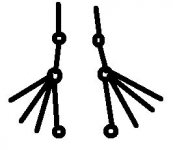
Here is a sketch for your reference.
The 0.1 poly has to be placed according to its intention. If it's purpose is to improve hf regulation, it has to be near the load. If it is for reducing ringing from the transformer diode combo, it should be close to the bridge.
Gajanan Phadte
The 0.1 poly has to be placed according to its intention. If it's purpose is to improve hf regulation, it has to be near the load. If it is for reducing ringing from the transformer diode combo, it should be close to the bridge.
Gajanan Phadte
Attachments
Hello and thank you very much for your help,
In this post I've attached another power supply PCB (at this time with high frequency filter capacitors for the bridge rectifier and also for providing some high frequency regulation.
I've also made another PCB (for TDA7297, TDA2822M and respective regulators), because TDAs in general need to have input ground directly connected in the PCB (I saw in a datasheet), so I think that I can't have the input ground directly connected to the power supply star ground, power ground (pin 8) must be connected by low resistance track to signal ground (pin 9), so I've made a star ground arrangement in this PCB.
I've made anything wrong in the PCBs?
Thank you very much for your atention,
Best regards,
Daniel Almeida
Attachments
Last edited:
- Status
- This old topic is closed. If you want to reopen this topic, contact a moderator using the "Report Post" button.