Just tested my new build valve front end with TDA7294 on output.
The valve part works fine.
I am getting about 500mV 1MHz oscillation on the output of the TDA7294.
It was worse to start with and shorting out the two copper pours with a wire link improved things.
There is pretty much zero hum so I don't think it is a ground loop.
The gain of the TDA7294 is set to about 5 to adjust for the extra gain from the valve stage. If I put in the recommended 22k the oscillation gets much bigger but lowers in frequency to about 100KHz.
If I turn my volume control down to zero the oscillation gets worse. Turning up the music reduces the oscillation. SO perhaps it is a ground issue. The circuit zero volt line is earthed.
The TDA7294 also pops on power down. I am taking the valve heater supply from negative rail so it could be because that rail is discharging first on power down.
An externally hosted image should be here but it was not working when we last tested it.
An externally hosted image should be here but it was not working when we last tested it.
An externally hosted image should be here but it was not working when we last tested it.
Last edited:
Did some more experimentation.
Took valve out. Powered up and the TDA7294 gives out a burst of oscillation for a second then it disappears completely.
With the valve in the oscillation burst starts and then never goes away.
Took valve out. Powered up and the TDA7294 gives out a burst of oscillation for a second then it disappears completely.
With the valve in the oscillation burst starts and then never goes away.
C3 would be more useful if you could get it closer to the IC. That would lower the inductance between the capacitor and the IC.
You may also need a smallish electrolytic cap (10-22 uF) in parallel with C3 and C9. I don't know the TDA chip you're using, but the LM3886 gets rather cranky if you remove the small electrolytic cap. High-power opamps like the LM3886 and TDA... are a bit sensitive to the decoupling networks due to their large current drive capability.
It sounds like the TDA... is oscillating. It should be able to start up and power down without spurious oscillation with its input shorted to ground. If it can't I'd figure out why and fix it.
Tom
Also: If the TDA... simulation model is reasonably accurate and includes the supply interactions, you could potentially tease this apart by simulating the power supply network with the IC.
Tom
Tom
I managed to tame the valve with a larger grid stopper and a 100pf capacitor. The valve was amplifying all sorts of out of band noise especially when volume control was at full when it would hum badly and hiss.
A 100pf across inverting and none inverting inputs stopped TDA7294 oscillating.
A 100pf across inverting and none inverting inputs stopped TDA7294 oscillating.
Last edited:
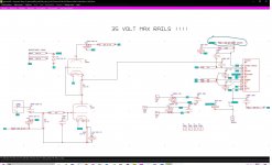
I enclose working schematic and latest pcb layout.
The 12au7 input capacitance is very low so I needed an external capacitor to work with the 47K grid stopper.
The 12au7 input capacitance is very low so I needed an external capacitor to work with the 47K grid stopper.
An externally hosted image should be here but it was not working when we last tested it.
An externally hosted image should be here but it was not working when we last tested it.
I have changed the heater circuit to work off the B+ rail to GND.
This means the positive rail will collapse first and make the TDA7294 go into standby/mute before negative rail dies.
This means the positive rail will collapse first and make the TDA7294 go into standby/mute before negative rail dies.
I have done quite a bit of research into the oscillation problem.
One thing I found was the feedback resistor runs miles away form the TDA7294. This is not recommended as the tracks to can be as much as 1nH per mm. This would explain the oscillation.
So I managed to bodge the circuit by putting a 1000nF across inverting and non-inverting inputs. The valve version gets away with 100pf as it has less gain. The plain TDA7294 circuit with more gain requires 1000pf.
So another project and learned a few lessons from it.
Despite the problems the results, especially the valve version, sound very good.
I needed a pcb made for a different project so added the latest version of the TDA7294 + valve amp to the order for $5 ! Good old China PCB Prototype & Fabrication Manufacturer - PCB Prototype the Easy Way
Built up a new pcb and it is very clean and sounds good.
Built up a new pcb and it is very clean and sounds good.
Some general points.
The tracks on op amp inputs should always be as short as possible.
Decoupling V+ pin to Ground to V- pin should always be as short as possible.
The output signal should be kept away from the inputs as much as possible.
The input line to the chip amp could be filtered to get rid of anything well above audio band.
Sometimes the layout can be made a lot better by careful use of smaller (lower wattage) resistors.
These chips look simple to use, but actually there is a lot of art in using them well.
People who design stuff like this in commercial products often go through several PCB iterations too.
These chips look simple to use, but actually there is a lot of art in using them well.
People who design stuff like this in commercial products often go through several PCB iterations too.
My main problem was the feedback resistor being too far from TDA.
This caused 1MHz oscillation.
I bodged that pcb with 1000pf across inverting and non-inverting inputs.
As oscillation waveform starts it is fed back straight away into none inverting input and cancels out.
The valve made the problem worse by picking up the 1MHz and amplifying it ! This then just went around loop. 100pf across grid to ground filtered it out.
I am gathering the parts
Can i substitute 12AU7 by 6111WA or 6N16B?
Do I need to change any parts by the substitution ?
Can i substitute 12AU7 by 6111WA or 6N16B?
Do I need to change any parts by the substitution ?
I am gathering the parts
Can i substitute 12AU7 by 6111WA or 6N16B?
Do I need to change any parts by the substitution ?
They are 8 pin valves, the 12au7 is a 9 pin valve.
They also need a bit more heater current so the heater voltage dropper resistors would need to be changed.
I get my 12au7 from RS Components and they are the cheapest I could find.
need clarification of R4 values.
Is this 22K +4K7?? ie 26K7
That resistor alters the gain.
Its 4k7 for valve version.
The 22k is for if the valve isn't used.
Its a dual purpose pcb.
- Status
- Not open for further replies.
- Home
- Amplifiers
- Chip Amps
- TDA7294 woes, 500mV 1MHz oscillation on output.