sorry for the late reply, im making this amp again in 3D printed Housings to match the 3D printed speakers i make
sorry for the late reply, im making this amp again in 3D printed Housings to match the 3D printed speakers i make
Nice. Looking forward to the pics!
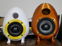
Here's the old version of 4" and 1' version of 5" (will have new design to hide screws under ring), 4" will also have oval port
Amazing. Well done
Hello guys!
On the 4th page I saw that you can use TDA7294 in bridget mode and get around 480W at +-22V.
Can anyone please show me the shematic for this kind of configuration?
Thanks
On the 4th page I saw that you can use TDA7294 in bridget mode and get around 480W at +-22V.
Can anyone please show me the shematic for this kind of configuration?
Thanks
Hello guys!
On the 4th page I saw that you can use TDA7294 in bridget mode and get around 480W at +-22V.
Can anyone please show me the shematic for this kind of configuration?
Thanks
That would be a miracle!
I am still pressed for time to even finish the Ali 7294 boards I bought (every time I leave them lying around for half a year I have to redo all my checking to see what errors the PCB has or what changes would work to get better low-end output...)
But I would love to see a schematic for the bridged TDA7294 setup!
I think I would manage to figure it out myself, but I prefer to make 'learning' mistakes with cheap stuff, not with obsolete 20 year old chips...
But I would love to see a schematic for the bridged TDA7294 setup!
I think I would manage to figure it out myself, but I prefer to make 'learning' mistakes with cheap stuff, not with obsolete 20 year old chips...
But I would love to see a schematic for the bridged TDA7294 setup!
You just need an inverting bridging circuit.
Quite easily done with an op amp.
See datasheet.
BRIDGE APPLICATION
Another application suggestion is the BRIDGE configuration, where two TDA7294 are used, as shown by the schematic diagram of figure 25. In this application, the value of the load must not be lower than 8 Ohm for dissipation and current capability reasons. A suitable field of application includes HI-FI/TV subwoofers realizations. The main advantages offered by this solution are:
- High power performances with limited supply voltage level.
- Considerably high output power even with high load values (i.e. 16 Ohm). The characteristics shown by figures 27 and 28, measured with loads respectively 8 Ohm and 16 Ohm. With Rl= 8 Ohm, Vs = ±25V the maximum output power obtainable is 150 W, while with Rl=16 Ohm, Vs = ±35V the maximum Pout is 170 W.
Circuit dynamic power amplifier with TDA7294 - bridge 180W or stereo 80W - Xtronic
Last edited:
Did anyone do analyses or, even better, measurements with these setups? One might be afraid that the drop-in of the additional power devices might cause distortions.
Btw, you know that there are applications with additional power darlingtons BDX53 and BDX54 in either the TDA7293 and TDA7294 datasheets? I don't know if these are class G or H, though.
Best regards!
Btw, you know that there are applications with additional power darlingtons BDX53 and BDX54 in either the TDA7293 and TDA7294 datasheets? I don't know if these are class G or H, though.
Best regards!
nobody try to use the same schematic as LINN ?
https://static.qobuz.com/info/IMG/jpg/Amplificateurs.jpg
GB2405275A - A discrete transistor boost amplifier for an audio driver IC, wherein the boost amplifier is automatically activated at high output levels
- Google Patents
Mao Audiophile Modifications: A Linn Klimax Chakra 500 Twin rescued from the last flood
It look like DR frost schematic but with other values, base resistor and inductance on emiter
Last edited:
Am I blind or are those "emitter inductors" in reality just a bus wire ran thru twin ferrite beads?
GB2405275A : The secondary amplifier includes inductances (L1, L2) for extending a switching off period of the secondary amplifier to smooth any switching discontinuity.
https://uk.farnell.com/murata/bl02r...17.511871610.1550072650-1056206696.1550072650
The BL02 series from Murata are radial leaded EMIFIL ferrite beads inductor to produce a high frequency loss for suppression of noise. These inductor type EMI suppression filters are designed to operate from several MHz to several GHz. They are widely used as general purpose noise suppression components to cope with relatively minor noise issues. EMIFIL Inductor type filters behave as inductors with small inductance at low frequencies, while they produce a resistance dominated impedance at high frequencies. When serially inserted into a noise transmission path, the resistance component absorbs and prevents the transmission of noise.
BL01/02/03 series are ferrite beads with lead wires to
produce a high frequency loss for suppression of
noise. Simple construction and easy-to-use, effective
for low impedance circuits such as power supplies and
grounds. Effective also for preventing overshoot and
undershoot of digital signal in clocks or the like,
and suppressing the higher harmonic wave. Suitable for
prevention of abnormal oscillation at high frequency
amplifying circuit.
Last edited:
Send circuits
Hello dr frost & all diyers
I still lay about amplifiers. and I am so excited to make this amplifier. I plan to make dual mono. This layout I would use. Please be corrected.
View attachment 356400 View attachment 356401
if any body have schematic opamp stereo/bridge with selector mode, please share .
I want to pair it with this amplifier.
Sorry if my English to bad.
Hello,
can you help me please with bug in my circtuit, im trying to build something very similar as this amp in this topic. But all what i get is fully open Q3 in this circuit, and dc in speaker.
Shared album - Andris Drulle - Google Photos
Have a nice day.
can you help me please with bug in my circtuit, im trying to build something very similar as this amp in this topic. But all what i get is fully open Q3 in this circuit, and dc in speaker.
Shared album - Andris Drulle - Google Photos
Have a nice day.
Hello,
can you help me please with bug in my circtuit, im trying to build something very similar as this amp in this topic. But all what i get is fully open Q3 in this circuit, and dc in speaker.
Shared album - Andris Drulle - Google Photos
Have a nice day.
did you get it to work?, cause you got no feedback in that circuit you posted, check the original i posted here
did you get it to work?, cause you got no feedback in that circuit you posted, check the original i posted here
nop, i didnt get to work.
But isnt PIN2 feedback? In circuit I posted I have 22k coming from out and 680R grounded.
nop, i didnt get to work.
But isnt PIN2 feedback? In circuit I posted I have 22k coming from out and 680R grounded.
update,
An externally hosted image should be here but it was not working when we last tested it.
ping 1,4 wasnt grounded, but this does not changed anything, im starting to think maybe my TDA is faulty.
- Home
- Amplifiers
- Chip Amps
- TDA7294 + Power Transistors AMP (TDA7293 to come also)