ok now rectifying...
SI-D 200V 8A/80Ap 10ns how do you think? its around 0.70$ do you think its an overkill?
SI-D 200V 8A/80Ap 10ns how do you think? its around 0.70$ do you think its an overkill?
Not overkill 🙂
There are many choices,
GSIB2560-E3/45 - VISHAY GENERAL SEMICONDUCTOR - BRIDGE RECTIFIER, 25A, 600V | CPC
or this style,
GBPC3504 - FAIRCHILD SEMICONDUCTOR - BRIDGE RECTIFIER, 35A, 400V | CPC
Everyone has there own ideas... I would suggest somthing like two 4700uf to 6800uf reservoir caps and also a simple snubber network of a 0.1uf 400vac poly cap in series with a 4.7 ohm 1 watt resistor connected across the combined secondary winding of the transformer (so that is across the input to the bridge)
heh... diode bridges cost about as much as a diode 😛 well that means i dont have to make one myself 😀
http://www.datasheetcatalog.org/datasheets/166/250526_DS.pdf
it says max current with 300cm^2 fin is 10A... if i devide 300cm^2 by the 10A, i get about how much cm^2 i need to cool that current, dont i? (i know it would be really rough, but if i round it up, i think there shouldent be a problem...)
http://www.datasheetcatalog.org/datasheets/166/250526_DS.pdf
it says max current with 300cm^2 fin is 10A... if i devide 300cm^2 by the 10A, i get about how much cm^2 i need to cool that current, dont i? (i know it would be really rough, but if i round it up, i think there shouldent be a problem...)
You won't have a problem with that. You'll find for normal loud music from the amp that the bridge is running cold.
could you draw the schematic?
i was thinking, that one or two large enough caps would do the trick...
also i know that there are caps before the bridge sometimes... i wanted to ask in wich cases... i guess thats for safety, so it doesnt spike, am i right?
i was thinking, that one or two large enough caps would do the trick...
also i know that there are caps before the bridge sometimes... i wanted to ask in wich cases... i guess thats for safety, so it doesnt spike, am i right?
Lets just go back a bit...
Designing an amp for 100 watts or even just 40 watts RMS and designing it so that it can supply that on a continuos basis is a whole different ball game to a nominally specified 40 or 100 watt amp that would be used for normal domestic listening. Heatsinks, transformers etc need to be much larger. Most amps you buy fall into the latter category in that they are for domestic use. Its a big big difference you have to understand.
So for "normal" use your transformer and bridge are fine. The bridge (if its a block type) can be bolted to the chassis if you wish.
Caps on or before the bridge are to stop "ringing" caused by the commutation of the bridge as it comes in and out of conduction... remember I said earlier that it was non conducting for most of the time... it is that switching each cycle that can cause the ringing in combination with the inductance of the transformer.
One cap and one resistor is all you need across the input to the bridge.
There's nothing to draw really. It's just the basic transformer/rectifier reservoir cap arrangment.

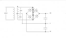
here... i drew a quick sketch... this is what i call basic transformer/rectifier reservoir cap arrangment. you said something about a rezistor... and what caps should i use...
Like this. Use around the values suggested earlier such as a 0.1uf and 4.7 ohm.
Grounding is SUPER SUPER important and makes or breaks an amplifier.
Read this 🙂
http://www.diyaudio.com/forums/solid-state/101321-3-stage-lin-topology-nfb-tappings.html#post1623053
http://www.diyaudio.com/forums/soli...-lin-topology-nfb-tappings-2.html#post1624677
Grounding is SUPER SUPER important and makes or breaks an amplifier.
Read this 🙂
http://www.diyaudio.com/forums/solid-state/101321-3-stage-lin-topology-nfb-tappings.html#post1623053
http://www.diyaudio.com/forums/soli...-lin-topology-nfb-tappings-2.html#post1624677
Attachments
I also wanted to make a equalizer, and i came up with this design (the ground here is the input ground (if that wasnt obvious)) dunno if this would work, but i think it should... maybe would mess up the sound really bad...

you mean grounding, when i connect the amp to the supply?
Not really 🙂 I mean the way you arrange and connect all the grounds electrically because although they are essentially the same point, the resistance of the wire and PCB print means that electrically they are not. This is the number one cause of amps that are unstable and amps that have noise and hum and buzzes.
A passive equalizer like that is BAD 😀 Don't even think about it...
i knew that it wouldent be good in the beginning, but few moments later, (when i was going to sleep) i realized, that eaven if it would not have noises, then with lower hz tuners i would also adjust the higher pitches 😀 😀
later today i realized, that i can make an equalizer as another project and use the 5v of pc usb port as supply voltage for an active equalizer... but thats for another time 😀
later today i realized, that i can make an equalizer as another project and use the 5v of pc usb port as supply voltage for an active equalizer... but thats for another time 😀
http://www.datasheetcatalog.org/datasheet2/9/0ozxelyhtgfl5jsx9108fj3sqq3y.pdf
so i wanted to choose a heatsink for the chip... i know that the formula is
T(Max)=P(dissipated)*(R(chip)+R(from chip to heatsink)+R(heatsink))+T(room)
so from the datasheet i get it like this
70=35(1.5+0.25+X)+25 (the room temperature is about 25, and with termopaste R(from chip to heatsink) is about 0.25)
so i will decrease the max temperature by 15 (just for safety)
55=35(1.5+0.25+X)+25 --> 30/35=1.75+x
0.86=1.75+X --> X=-0.89 ... my question is... why is it negative... the rezistance cant be negative...
oh... so what do you suggest? (about grounds)
You need to fully understand the problem and its one whole big subject in itself.
The main points are that the connection between the two reservoir caps is not to be used as a ground point itself. You take a small (any length) spur off that connection and the end of that becomes our reference point or audio ground. Its electrically clean and has no current from the PSU lowing in it. This point is used as a star that the other signal grounds return too.
Heatsinks... I've never done thermal calculations and always choose empirically with an eye on the degrees C/per watt rating 🙂 Again this is where the difference between pro and domestic applications come to the surface. The TDA7293 type chips might be rated at 100 watts RMS but in practice you are never going to get that heat away from the chip fast enough. So you compromise and choose something thats acceptable for your use.
Something like this,
350AB1000B - ABL HEATSINKS - HEAT SINK, 0.67°C/W | CPC
im sorry... spur?
oh... well i want to know hos small of a heatsink i can use, because thoes things are expensive,,, i have two that i guess are too small... also, i have to get two of them... (for each channel)
oh... well i want to know hos small of a heatsink i can use, because thoes things are expensive,,, i have two that i guess are too small... also, i have to get two of them... (for each channel)
i actually have a heatsink, from some old russian device, but i am 76.352% sure, that it wont do
- Status
- Not open for further replies.
- Home
- Amplifiers
- Chip Amps
- TDA7293 datasheet