Hello,
Yes, so it is not audio use, or not directly.
In my turntables, I'm using a double DDS generator to run my Airpax/Premotec motors. For that I'm using LM3886 based amp modules, 2 channels. That is not a straight choice I think, I had some ringing problems before I've inserted 2 antiparallel 47uF caps at the output of the chipamps, but I always wanted to try TDA7293 because I saw some others use those without problems.
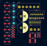
Now I need a 3 channel amp (also building a 3 channel DDS gen) and there is no ready made 3 channel module, so I've decided to make one. I have power supplies, so did not put it on the board, but plan to use a simple Graetz and 4x 22mF caps.
So, if you have experience with these chipamps, would you have a look?
As I know the feedback resistors has to be placed the closest possible (some even solder on the IC legs) and obviously in/out has to be separated. Any other thing to watch?
On other threads, there was links to a document listing pitfalls in implementing amp with TDA7293, but the link does not work any more :-(
Thanks!
JG
Yes, so it is not audio use, or not directly.
In my turntables, I'm using a double DDS generator to run my Airpax/Premotec motors. For that I'm using LM3886 based amp modules, 2 channels. That is not a straight choice I think, I had some ringing problems before I've inserted 2 antiparallel 47uF caps at the output of the chipamps, but I always wanted to try TDA7293 because I saw some others use those without problems.
Now I need a 3 channel amp (also building a 3 channel DDS gen) and there is no ready made 3 channel module, so I've decided to make one. I have power supplies, so did not put it on the board, but plan to use a simple Graetz and 4x 22mF caps.
So, if you have experience with these chipamps, would you have a look?
As I know the feedback resistors has to be placed the closest possible (some even solder on the IC legs) and obviously in/out has to be separated. Any other thing to watch?
On other threads, there was links to a document listing pitfalls in implementing amp with TDA7293, but the link does not work any more :-(
Thanks!
JG
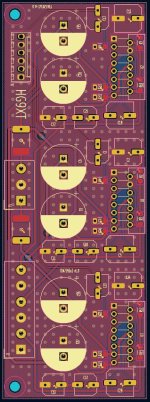
Attachments

Surprising that the amplifiers stay stable with a 23.5 uF capacitive load. It probably helps that the capacitors are rather lossy.
It is about 3x5W with the bigger motor, but the 1mF on the board is just to have a cap close as well, in the psu pcba I have 4x22mF.The filter capacitor bank you're thinking of makes me scratch my head about the power requirement of a TT motor 🤔.
Best regards!
With the LM3886 it is needed. I will start the TDA without the caps and test it. The motor is very indulctive load. The LM3886 was “ringing”without the caps at the output (I do not remember now it was at zero cross or at peak, but saw it on oscilloscope and actually it was noticeable when I was holding the unloaded, rotating motor in my hand.Surprising that the amplifiers stay stable with a 23.5 uF capacitive load. It probably helps that the capacitors are rather lossy.
On the other hand, the TDA may not need it at all.
Thanks moriarti for looking at it! What do you mean? As I see the +VA is the "ON" status. I do not need the mute and standby function at all here. I know the datasheet suggests an RC delay circuit there, but to get an initial pop transient at switch on is not a problem for the motor it will drive. That is why I've removed them. First, I had them on, but while I've optimized for shortest distance on feedback resistors and putting close the bootstrap cap, I've removed them.
Do you say it will not work this way, or just say it will let the start transient go out on output?
Thanks,
JG
Do you say it will not work this way, or just say it will let the start transient go out on output?
Thanks,
JG
Add a small output resistor that will help with stability on reactive loads.
It will be enough to add 1R0 since you don't have heavy motors. In any case, calculate the required resistor power after calculating the thermals.
You can also iclude the output resistor inside the NFB loop (R3-R10-R15 22K).
You can also add RemoteSense, an NFB extension that will control the response directly at the motor terminals (4 wire => Force & Sense).
Then the output resistor can be outside the (local) NFB, RemoteSense (global NFB) will include it anyway!
Years ago I designed something similar with PID LME49720+LM3886 in CompositAMP, also for a Turntable motor,
input it was controlled from a special DAC that generated the necessary Sine wave for ACmotors...
Last edited:
Probably a piece of schematic says 1000 words...
In Bold ForceHot and ForceCold connections to the motor, make twisted pair.
Also SenseHot and SenseCold go together in twisted pair connection for Kelvin sensing method.
Wires can be long if you need...
TDA7293 must have local gain of 26V/V or grater for stability (DS), if you need lower TOT gain, left local gain (1 + 22K/680R) = 33,4V/V
and use input atenuator to reduce the TOT gain,
match +IN and -IN impedance for smallest OUT DCoffset, or add additional DCoffset adjust trimpot
Above ATT = (22K+47R)/(680R+22K+47R) =0,97V/V
TOT Ao_gain = 32,4V/V
Giordano, there is always something I forget to add,As I know the feedback resistors has to be placed the closest possible (some even solder on the IC legs) and obviously in/out has to be separated.
if the PowerAmp (in general all opamps) has a high enough OLG,
then in the ClosedLoop application it keeps the input signal reference (input: audio, DCref, DC+AC, whatever...) as accurate as possible at the NFB extraction point, so:
-The feedback resistors has to be placed the closest possible (some even solder on the IC legs),
OK,
then NFB will monitor this very point (IC OUT pin->NFB extraction point), and this point will become a faithful copy of the input signal as possible
with OLG ability to correct errors in ClosedLoop
But how will the NFB now know what is happening at the remote load (read connection RLC parasitics), where we want an amplified copy of the input signal?
-What about RemoteSense (RS),
the NFB extraction point becomes the connection point(s) of connected points of Sense lines = alias Kelvin sensing in measurement terminology
So,
in audio with PowerAMP it is almost best to control with NFB the AMP Speaker terminals on Chassis,
rather than, for example, the output of the AMP on the PCB
where the highest DampingFactor will then be, unless we have RemoteSensing planned Ahead and then monitor directly Speakes terminals.
I have been planning it in the designs for years now in every single one of my AudioAMP projects, even though customers then don't use them!!!
Ha,
they rather prefer to buy very expensive/fensy speaker cables, instead of eliminating the influence of cables (of any quality) SIMPLY by using RemoteSense right on the Speaker terminals!
🙂
Also, the PowerAMP with its NFB keeps the output impedance very low, in the microR range if the OLG is high enough (use composit),
guess what, so we have very low impedance right at the RS extraction point => here, on motor connector!
Ha,
someone will just say: This is "OverKill"!!!, so what!!!... if we have the opportunity to use it, ....and very cheaply!
Last edited:
This is interesting. Thank You so much. I appreciate you even put effort in drawing !
To be honest, I was thinking about standby as a feature I do not need. I thought it is just to save energy, but I just switch off completely, so I thought I do not need the standby. Similar on mute. I thought the motor will not care about the switch on pop. The reason why I've removed is not the cost of the few parts, that is on order anyway, but the complexity and to make things more clean. But, I realize now that it is not just features, it is requirement. Thanks.
It is also interesting, that charging the cap on mute is through 32k, but for discharge 22k of that is shorted to get muted first when powering off. OK. Makes sense, strange that it is not in the datasheet.
On the output series resistor, I've tried it with the LM3886, played with different resistors from a few .1 Ohm to about 47 Ohm. Did not help. Only the cap helped. ... but, that is a different chip, different output (* by the way, I would have another, general question about it at the end). I put a place for it at least, maybe shorting at the beginning and will see.
On the remote sense, that probably would not help because the 3 phase motors so far I have are Papst 110V or 220/230V motors, so I need 3 transformers at the output, which is right next to the amp pcba. For my 24V Airpax/Philips motors, I have LM3886 based amps, my curiosity will make me try it, but I do not intend to replace the module.
Another question I would have is:
The reason why I've picked TDA7293 now is because I saw 2 companies using it for motor driving, including AN, driving 3 rather large motors in the new TT-3 (since the old 2 phase Papst motor used by Voyd is not available any more for long). I have not seen LM3886 in motor driving at all. Maybe the FETs are better suited for this job? Or, I've also heard that this TDA7293 is originally designed as a high power instrumentation amplifier and from there it was optimized for audio while LM3886 was originally designed for audio. I do not know it is true, but if it is, that may explain why it is a better fit for this alien application.
Thanks!
JG
Mute and STBY are not crucial for the load/motor itself, but rather for internal stages TDA7293 to StartUP correctly,
for IPS and VAS, as well as for all other internal protections, before we even load the output of the output PowerBuffer!
...that it is not just features, it is requirement, as you yourself mentioned earlier.
Look in DS page 9/21; Figure 5 ,Suggested turn-on/off sequence & Figure 6 ,Single signal standby/mute control circuit.

That output resistor is crucial for system stability on reactive loads, you may include it in NFB loop, in this way you also have low output impedance regardless of the imposed resistor. So still high Damping factor regardless of additional Rout!+
The motor looks quite reactive in character, it would be necessary to measure what it has cos(φ) or motor power factor, the phase angle between voltage and current (-> cosφ) and based on this then determine the necessary compensation Cx
or experimentally, using an oscilloscope, two-channel, and trimming the necessary compensation until we have the right shape of the sine wave on the motor compared to the input sine wave to TDA7293.
LP
Dragan
for IPS and VAS, as well as for all other internal protections, before we even load the output of the output PowerBuffer!
...that it is not just features, it is requirement, as you yourself mentioned earlier.
Look in DS page 9/21; Figure 5 ,Suggested turn-on/off sequence & Figure 6 ,Single signal standby/mute control circuit.
That output resistor is crucial for system stability on reactive loads, you may include it in NFB loop, in this way you also have low output impedance regardless of the imposed resistor. So still high Damping factor regardless of additional Rout!+
The motor looks quite reactive in character, it would be necessary to measure what it has cos(φ) or motor power factor, the phase angle between voltage and current (-> cosφ) and based on this then determine the necessary compensation Cx
or experimentally, using an oscilloscope, two-channel, and trimming the necessary compensation until we have the right shape of the sine wave on the motor compared to the input sine wave to TDA7293.
LP
Dragan
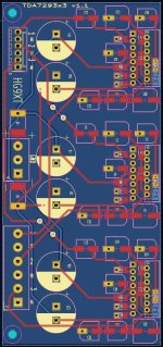
Attachments
sooo, it does not work :-(
The mute, standby seems to work, however it looks odd to me that mute goes much higher. I guessed some internal circuit would clamp it to ~ 5V, but not on the mute.

Anyway, that is not the main problem, the main problem is that even I set 1A max current on the lab psu, the negative supply is getting on constant current immediately with near zero voltage. Like it is shorted, but it is not shorted. If I switch on the negative only, it takes about 100mA (on 3 ic).
The output it on about 8V DC, which is not a surprise, since power rails are on +21V and -0.1V because the cc triggered on the negative supply.
If I go down to + - 12V, it takes about 150mA from both, but the output is still on +DC, about 2V and it does not change, not matter what I connect on the input. It just stuck there.

The truth is, I've soldered in TDA7293s from Aliexpress. My plan was that I try with that and if it works well, I replace from Farnell. On the ohter hand, that should work too.
There is no oscillation.
... any advice appreciated ...
Thanks,
JG
The mute, standby seems to work, however it looks odd to me that mute goes much higher. I guessed some internal circuit would clamp it to ~ 5V, but not on the mute.
Anyway, that is not the main problem, the main problem is that even I set 1A max current on the lab psu, the negative supply is getting on constant current immediately with near zero voltage. Like it is shorted, but it is not shorted. If I switch on the negative only, it takes about 100mA (on 3 ic).
The output it on about 8V DC, which is not a surprise, since power rails are on +21V and -0.1V because the cc triggered on the negative supply.
If I go down to + - 12V, it takes about 150mA from both, but the output is still on +DC, about 2V and it does not change, not matter what I connect on the input. It just stuck there.
The truth is, I've soldered in TDA7293s from Aliexpress. My plan was that I try with that and if it works well, I replace from Farnell. On the ohter hand, that should work too.
There is no oscillation.
... any advice appreciated ...
Thanks,
JG
Attachments
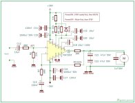
I'm not familiar with this circuit. What strikes me are the reversed 47uF electrolytic capacitors; they don't make sense, and the reversed coupling capacitor in the input is unusual.
Try replacing the 10uF electrolytic capacitor in the input with a 1uF film capacitor, and in the output, I would replace the two 47uF electrolytic capacitors with an RC Zobel element (4.7 ohms and 0.1uF). C2 and C5 should be 22uF. 100uF for the bootstrap is too much, and the negative feedback with 47uF might also be too much!
Try replacing the 10uF electrolytic capacitor in the input with a 1uF film capacitor, and in the output, I would replace the two 47uF electrolytic capacitors with an RC Zobel element (4.7 ohms and 0.1uF). C2 and C5 should be 22uF. 100uF for the bootstrap is too much, and the negative feedback with 47uF might also be too much!
I tried that once. Great if you have a lot of rail fuses you need to use up!The truth is, I've soldered in TDA7293s from Aliexpress. My plan was that I try with that and if it works well, I replace from Farnell.
I never had one from Ali, that worked properly, but all the ones from reputable sources do.
Don’t waste time time trying to fix a circuit with an Ali chip in it, all you know about it is that it looks about right and has the right number of pins.
Yours too:Hello,
Yes, so it is not audio use, or not directly.
In my turntables, I'm using a double DDS generator to run my Airpax/Premotec motors. For that I'm using LM3886 based amp modules, 2 channels. That is not a straight choice I think, I had some ringing problems before I've inserted 2 antiparallel 47uF caps at the output of the chipamps, but I always wanted to try TDA7293 because I saw some others use those without problems.
Now I need a 3 channel amp (also building a 3 channel DDS gen) and there is no ready made 3 channel module, so I've decided to make one. I have power supplies, so did not put it on the board, but plan to use a simple Graetz and 4x 22mF caps.
So, if you have experience with these chipamps, would you have a look?
As I know the feedback resistors has to be placed the closest possible (some even solder on the IC legs) and obviously in/out has to be separated. Any other thing to watch?
On other threads, there was links to a document listing pitfalls in implementing amp with TDA7293, but the link does not work any more :-(
Thanks!
JG
Bootstrap capacitor too large (22uF is optimal), negative feedback capacitor too large (22uF is optimal). The gain should be a maximum of 30x. Reduce the input capacitor to 1uF and ensure that the polarity is correct. Connect an RC element (4.7 ohms + 0.1uF) between the output and ground. Then nothing should oscillate.
TDA7293... the exploding amplifier IC. Do you know this?
Forgot the why and the how but recall having replaced quite a few.
Forgot the why and the how but recall having replaced quite a few.
You might want to be careful with electrostatic discharge; the TDA7293 is very sensitive to it. I've only had one problem so far, and that was due to an electrostatic discharge that damaged a TDA7293.
Of course as it is DMOS but that was not the cause. It had to do with the IC itself having an error (mute and standby pins I recall) and the IC was produced in a few revisions. It does not help that today many unreliable fake/counterfeit TDA7293 are sold. TDA7265 has similar sudden failure. I then repaired Linn amplifiers that had these ICs and these were definitely original. Saw so many defective ones with holes burnt in the casing that I skip every product with either TDA7293 or TDA7294 since then.
Anyway, the tip is to never buy such ICs on Aliexpress. If the older original ones and the new copied ones both can be unreliable one better buys them carefully. Or just skip them.
Anyway, the tip is to never buy such ICs on Aliexpress. If the older original ones and the new copied ones both can be unreliable one better buys them carefully. Or just skip them.
Last edited:
- Home
- Amplifiers
- Chip Amps
- TDA7293 alien use