I correctly understood about tda7292. If you have tda7265 pcb layout with mute functioning please post.
i will post it , the layout later in the evening i late to work tright now. hmmm secondly i havent used the mute pin as i didnt need it. but if kept floating it works fine, i m using it like htat since a few years with out a blow up.
NO MY AMP IS NOT WORKING/SOUNDING
How I completed my job : Gain Resistor (22+1) Power Supply 18-0-18 Split Supply. My audio source is CD Player.
1) When the Power switch ON, speaker starts continues humming. But amp sounding very very poor with humming/distortion. I Checked properly and found Pin 1 (-) Supply not connected to Pin 6. Power switch OFF & Pin 1 connected to Pin 6.
2) Again Power switch ON, Amp is like dead. I Checked again all & found no mistakes. DC was present at Pin 1 & 3 etc., Audio source was present in input Pin 7. No nothing Amp was not respond any way. I thought mute function was not working properly and I removed all required component from Pin 5 and make Pin 5 flotting/Not connected mode. No still amp was like dead. Power switch OFF
3) Again I disconnect Pin 6 from Pin 1, speaker starts continues humming. etc.,
Please help me what is my mistake.
Thanks & Best Regards.
i dont know what your board is like , post the track side here for a look, thn it will be easy to say whats wrong, try using the file i wold be posting and then let me know
and put all he componets i put.
and put all he componets i put.
I build on general dotted pcb, there is no tracks. Please post your pcb,schematic etc., all information.
Thanks & Best Regards.
Thanks & Best Regards.
i wold like to know what u are doing first i dont want to do spoon feeding, using a dot board, all the time is nto a good idea,
i want to see your assembled board, from both sides component and solder side.. i feel you have missed out on some part or its shorting some where, or u have not selected a proper gain level
i want to see your assembled board, from both sides component and solder side.. i feel you have missed out on some part or its shorting some where, or u have not selected a proper gain level
As per post # 23, I scraped everything.
Yesterday, I purchased new TDA7265 & required components and build again but this time Pin 2 Pin. And got success.
Build with...
1) Gain (22/1)+1 = 23 [ As per data-sheet (18/.560)+1 = 33 ]
2) Power supply 18 (+-) [ As per data-sheet 25W = 20 (+-) ]
3) Mute Pin kept floating
Observations :
1) Amp sounding not bad
2) Loudness poor.
3) POP at power ON/OFF
4) Chip running cool ( After 10 Min. continues running I touch the Chip & Heat sink near the chip mounted and found cool. Not warm even. )
As Chip is running cool I am not using it's full ability of this chip. Is it right ?
Alterations for Today :
1) I should try it with 18-0-18 Transformer.
2) I should increase gain = 33
Any advise ?
Thanks & Regards.
Last 3-4 days I was unable to build tda7265 because 1st time purchased chips was fake. I scraped 3 chips. Today I purchase again from another stores and it was genuine. Original & Fake both chips looks similar only one difference I found is fake's pins are more thick & short and original chips's pins are long & thiner. I think Indian market is full of fake chips.
I think Indian market is full of fake chips.
It's about the same here. I bought a TDA7294 a couple years ago, that had the same behaviour as your 7265. At first i forgot to connect the negative supply, the chip worked but sounded awful (reason is obvious). Then when i connected negative supply correctly the chip would not go out of standby mode, no sound output. Exactly like yours did.
It turned out to be fake. I bought another one and installed it on the very same PCB and it's still working today.
As per Post # 8 Picture I am building bridge where 5.6nf is not available at my regular suppliers. Is it 5.6nf = .56 uf ?
Thank you sangram, Now I understood conversion. I will ask for 5.6nf to my supplier. Is 5.6nf available in local mkt ? Or any substitute is possible ?
Another question is
1) For Input cap, Can I use 0.47uf 63v Polypropylene (.47K63) instead of 1uf 25v electrolytic for Satellite-Amp.
2) Till today, for 0.1uf I was using ceramic cap. But today I purchased 0.1uf 63v Polypropylene (.1K63) box type cap. It is yellow color. Is it better for Supply Voltage Bypass ?
5.6nF can be made by parallel combo of 4.7nF and 1nF - it's close enough, if you can't find the exact value.
Input capacitor value will form high-pass filter with Rin, you can use value larger than required - if reducing, then check what the new roll-off frequency is.
Ceramics work well enough for supply bypass. MKP caps can be used as well, there will be some reduction in microphonic behaviour of disc ceramics but I'm not sure about output noise. They would be similar.
Small yellow box types may be MKT (Polyester) or MKP (Polypropelene).
Success Story But problem with power supply.
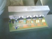
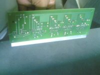
I purchased genuine chips. I always used general dotted pcb. Chips pin alignment was not match with general pcb. I visited to professional pcb fabricator and fabricated my design. But he asked for quantities. I ordered 10 nos. which was minimum qty. I build my design such way that four chips (5.1) mounted on single pcb including pre-amp (ne5532) for sub. (Bridge). Yesterday, everything was ready & tested with gain=33, transformer = 12-0-12 (Regulated Split Supply)
One thing which I was looking from couple of months is ( BUILD AMP LIKE PROFESSIONAL ) I think I achieved today. Now I have PCB like professional with masking & tinning.
Observations :
After all connections I power switch ON, as general practice I did not find any activity in the amp. The amp was like dead, I touched speaker no hum it was like dead. After 2-3 seconds, suddenly music/sound started and I found poor loudness with 4ohm speaker. ( I should try with 18-0-18 trafo ) After 5 minutes listening I power switch OFF. I think my amp is working correctly. There is no POP on switch ON/OFF.
My fault : I design pcb such way that ne5532 + tda7265 both power supply with single track. Maximum voltage for 5532 is 22v per rail. 7565 is 25 per rail. 15-0-15 trafo is not available to my supplier.
As I am using regulated supply, the amp's loudness poor ? I think some voltage is eaten by regulated chips.
I am looking for SINGLE POWER SUPPLY which will supply below the 22v rails to ne5532 and perfect 25v per rail to tda7265.
With the same configuration (post # 37) test again. I found if I touch mute capacitor 47uf 25v loudness increase but there is no weak/dry solder.
Measure the voltage from pin 3 to 5. There should be more than 6 or better more than 7 V to switch the amplifiers completely on.
- Status
- Not open for further replies.
- Home
- Amplifiers
- Chip Amps
- TDA7265 for multimedia speakers