So i ripped apart a set of sonic impact "portable speakers" to reuse the amplifier for use in a speaker in my kitchen. i sketched out the circuit in ExpressPCB and had a couple of questions about it:
(1) What are C19 and C20 being used for? My initial guess was treble pass, but the frequencies they're letting through seem to be really high (60K+??) There's just high frequency hash up there, right? When I rip them out, the circuit seems to sound better....
(2) What are C21 and C22? Low pass to filter out RF frequencies perhaps?
(3) The circuit after the coupling capacitors looks to simply be a copy of the TDA2822M datasheet circuit, with the exception of R27 and R28 in the output zobels (which are 2.2 ohm instead of the prescribed 4.7 ohms). The speakers were original NXT transducer types that were nominally 4 ohms, so shouldn't the zobel resistors have been larger? What effect would the different value have?
Attachments
I modified the circuit for use in my application, which is a mono speaker comprised of a 4" driver i salvaged from a computer "subwoofer" and a cheapie tweeter to assist on the high end. Since I had two channels, I decided to feed both of them the same signal and wire it up bi-amped (silly, i know, but all for the sake of fun). After lots of tweaking, I managed to reach a happy medium with the modified circuit (attached), which I still have a few questions about:
(4) R1 and R2 are a simple linesum to mix the stereo signal down to mono. They're small values (I have a big pack of 1% 620R lying around), but this amp's going to primarily driven off an airport express which has an output impedance of 15 ohms. Shouldn't have any problems, right?
(5) I swapped the original 50K pcb-mounted thumbwheel pot out for a 10K standard volume pot which I also had lying around. The original and the new one are both linear pots. I imagine it's working in parallel with R23 to form some sort or not-so-linear-but-not-quite-log curve, right?
(6) I originally ran the amp without R3, but then realized that the two channels in parallel was too low an impedance, resulting in bass distortion. Sticking R3 in seemed to fix this, but I still don't see how. The output from the pot sees an amp input impedance of ~ 8.9K, but conversely, doesn't the amp, looking backward from the coupling capacitor, see a driving stage with increased output impedance? Is there a better way to bridge the impedances? I was thinking to increase the values of R25 & R26, but am wary to do as it might open up a whole other can of worms I don't know about...
(7) R4 and R5 (from the same bag of 620R resistors!) are there to attenuate the signal to the more-efficient tweeter. I originally calculated the resistance in series with the amp's 10K impedance to get a 1dB drop in output, but this was before adding R3. Does the addition of R3 (and the output impedance of the previous stage in general) have any effect on the final amount that the tweeter gets attenuated?
Attachments
The speaker's sounding pretty decent now, and I'm inclined to leave well enough alone, but these are just a bunch of hey-i-wanna-know-how-this-all-works questions that sprung up along the way. Any enlightenment short of "bug off and go read a physics textbook" from you folks would be greatly appreciated.
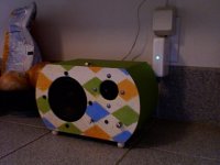
On that token, here's a picture of the amp, which has been about a dozen times more work than I original planned for. But it's so cute!
On that token, here's a picture of the amp, which has been about a dozen times more work than I original planned for. But it's so cute!
Attachments
Nicely done! I'm working on a TDA2822M mono circuit next year myself. Will host it on my personal website.
I'm puzzled as to why no one replied to this thread.
I'm puzzled as to why no one replied to this thread.
Last edited:
What I see when I look at the input section is a voltage divider to drop high offset voltages and a coupling cap to keep the signal intact. It should have a low pass filtering effect I would think but not a very tuned one. Capacitors 21 and 22 are not configured as filters however they may have been inserted in an attempt to reduce 'thermal noise' in the filters just ahead of them. It's and odd layout and as likely to introduce as many unwanted effects as it eliminates....if it eliminates anything.
What I find really different is the circuit arrangement between the chip outputs and the speakers. This appears to be a resonant circuit comprised of the caps, resistors and speaker thats totally wiped out by the track to ground right after the coupling cap. I'm tempted to simulate this circuit and run a frequency sweep on it it just to see if it actually has a defined band.
If someone has a handle on this layout I would love to hear the reasoning.
Last edited:
Ahh, of course. The output appears to be what I think is called a half section or Boucherot Cell. It's a constant impedance network (to flatten the response curve of the speaker?) but its shorted out. It should be on the positive side of the speaker as well... I think. Anyway, an outdated design that uses a lot of components compared to more modern filtering methods. Sometimes its as informative and interesting to see something thats (incorrect?) as it is to see the elegant solutions. Of course this means that I now have Zobel networks and constant impedance networks on my reading list....thanks.
- Status
- Not open for further replies.
- Home
- Amplifiers
- Chip Amps
- TDA2822M amplifier circuit questions