I have read many posts and watched many videos online about Tda2030A and 2040 amp chips. Many of those say that these chips work great even on single 12 Volts or 24 Volts. But when I made my own amp using these chips as single supply amp,I found that all those guys telling that it works on single supply was a big Lie!!
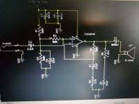
In fact, both Tda2030A and 2040 chips only output maximum 2 Watts on 24 Volts @ 8 ohms and 1 watt on 12 Volts @ 8 ohms load. Not only that, I found that component values given in the datasheet of Tda2040 for Single supply was not working in reality. But when I changed the values of Tda2040 to that of 2030A, the circuit was working ok in single supply. Please see my diagram. So the conclusion is that these split supply chips won't work to their Full at all on single 12 or 24 Volts
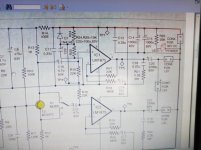
Also, please see the diagram for LM1875 on single supply. I'm sure it also won't output full power at Single 30 Volts as claimed by someone
In fact, both Tda2030A and 2040 chips only output maximum 2 Watts on 24 Volts @ 8 ohms and 1 watt on 12 Volts @ 8 ohms load. Not only that, I found that component values given in the datasheet of Tda2040 for Single supply was not working in reality. But when I changed the values of Tda2040 to that of 2030A, the circuit was working ok in single supply. Please see my diagram. So the conclusion is that these split supply chips won't work to their Full at all on single 12 or 24 Volts
Also, please see the diagram for LM1875 on single supply. I'm sure it also won't output full power at Single 30 Volts as claimed by someone
Attachments
Last edited:
The chip doesn't know the difference between single supply and dual.
If your experiments aren't producing the full expected outputs then you either have a construction error, a measurement error or duff chips.
The resistor values in your diagram are very high, for example 100k feedback resistor and 100k bias network. This can be a problem given the relatively high input bias currents of this chips.
100k and 4k7 feedback resistor values are taken from TDA2030 single supply application datasheet, for TDA2040 it should be 22k and 680E variation.
I doubt that this is the main problem for poor results. Biasing for mid voltage can be easily checked by measuring voltage on pin 4, it should be half of the power supply voltage. Reference is GND (ground).
I doubt that this is the main problem for poor results. Biasing for mid voltage can be easily checked by measuring voltage on pin 4, it should be half of the power supply voltage. Reference is GND (ground).
The maximum output power fully depends on the supply voltage. The maximums for the three ICs are TDA2030:36V/3.5A, TDA2040:40V/4A, LM1875:50V/4A. You never get maximum output power unless you use maximum supply voltage. Be aware that you remain below the current limits.
Your power supply has to remain at constant voltage when current is drawn. The small 100uF decoupling capacitor will do very little when you increase the output power.
Your power supply has to remain at constant voltage when current is drawn. The small 100uF decoupling capacitor will do very little when you increase the output power.
I am sorry for my conclusion about poor results, FauxFrench nicely said about power supply and voltage.
After some rethinking, it is normal to have only 1W RMS on 8 ohm load with 12 Volt power supply, 3,8W RMS with 24V power supply. That amp have efficiency of about 65%.
After some rethinking, it is normal to have only 1W RMS on 8 ohm load with 12 Volt power supply, 3,8W RMS with 24V power supply. That amp have efficiency of about 65%.
12V single supply, 8 Ohm load, what is the most power we can expect?
An ideal amplifier would swing 12V peak-to-peak. We read audio in Sine RMS. So divide by 2.828. 4.24V sine RMS. Power will be voltage squared divided by impedance. 4.24^2 is 18, divided by 8 is 2.25 Watts.
A real amplifier has losses. A good amplifier has small losses. We will get 1.6 to 1.8 Watts before clipping.
A company $ELLING amplifiers will crank-up to gross distortion. Allowing 10% THD can mean 20% more "power". So claims well over 2 Watts are "true", if not High Fidelity.
Black background picture should have C3 reversed.
If you built it as shown there may be some problems.
If you built it as shown there may be some problems.
@PRR
You forgot that datasheet says efficiency about 65%, so if you multiple that value to the output voltage you'll get what I calculated (about 0,95W/8ohm).
Results of test confirmed what I calculated.
@DUG
You observed well, C3 is reversed polarised in this situation (it will have + 6V-12V on negative pole of capacitor, depending on what power supply is fed).
Last edited:
@PRR
You forgot that datasheet says efficiency about 65%, so if you multiple that value to the output voltage you'll get what I calculated (about 0,95W/8ohm).
Results of test confirmed what I calculated....
Please show your calculations.
Efficiency of Class B is 78% at most, and 65% is typical, and that does not *directly* multiply the output.
Datasheet stated efficiency is fine (hey, they should know) but watch other parameters associated with it, such as supply voltage.
65%? ... cool, but result is valid at specified supply voltage.
When you lower supply voltage, specially as low as 12V single supply (or +/-6V dual supply,same thing) efficiency suffers, because you always have a fixed voltage loss caused by output and driver transistors saturation voltage.
Yes,a couple volts ... each side.
Not too important at higher voltage, performance killers at lower one, so at such values efficiency is *less* than 65%.
Most TDA20xx are designed for relatively high supplies; IF you know 12V is all you can get, switch to the "car radio" ones, which were optimized for that: the venerable TDA2003 which started it all and its "2 in 1" brother: TDA2005 .
Early versions such as TDA2002 and TDA2004 were soon obsolete and replaced by the ones I mentioned above.
In fact TDA2003 was uniquely designed to deliver 10W into 2 ohm, go figure.
TDA2002 was the one that started it all, not the 2003.
There were even some with gold-plated leads IIRC.
(I gues this particular knowledge makes me a good future candidate for the "old farts club"! Jay! Oh joy!)
There were even some with gold-plated leads IIRC.
(I gues this particular knowledge makes me a good future candidate for the "old farts club"! Jay! Oh joy!)
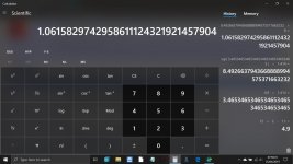
I would have said around 1.1 watts rms into 8 ohms. Calculation history at the right, read from bottom to top. Guestimate of a losing 1.1 volts on each peak into 8 ohms.
In your audit-trail I see 1.414 twice. I'm not sure why.
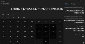
12V supply
1.1V lost each side
12V-1.1.-1.1V= 9.8V peak to peak
RMS of a Sine is peak to peak divided by 2.828 (2 * SqRt 2)
9.8V / 2.828 = 3.465V RMS
(here you seem to take 1.414 again?)
V^2/R is P
3.465V squared is 12.00
12V/8r is 1.501 Watts
FWIW: a "12V" amplifier "should" strive for less than 1.1V loss each side. This IS tough. Some chips do do better. If we get well below 0.6V each side we get close to 2 Watts. This will usually need bootstrapping, a complication and extra pin(s).
Yes, the 2020 series are aimed at higher voltage. As JMF says, the 2003 types were breakthroughs in low-voltage work. The '2003 output stage "can" have 0.1V loss (Vce) on the down-swing, 0.7V loss (Vce+Vbe) on the up-swing. For 12.00V supply this gives 11.2Vpp or 3.96Vrms swing. Losses increase with loading, but seem to stay small at 8 Ohms and tolerably small for lower loads.
Last edited:
In your audit-trail I see 1.414 twice. I'm not sure why.
Well spotted 🙂 No idea what happened there, I must have got distracted I guess.
Attachments
100k and 4k7 feedback resistor values are taken from TDA2030 single supply application datasheet, for TDA2040 it should be 22k and 680E variation.
I doubt that this is the main problem for poor results. Biasing for mid voltage can be easily checked by measuring voltage on pin 4, it should be half of the power supply voltage. Reference is GND (ground).
I changed the values coz the original values 22k & 680 ohms were causing the chip to shutdown frequently after few seconds.
Check if you have genuine chips as these are obsolete parts & many fakes are floating around. I used TDA2030 with default components value, single supply 19V laptop adaptor with 8ohms spk. It was pretty loud. I did not measure output power but total power consumption was 6W on energy meter for stereo setup with light music playing on full vol thru mobile.
- Status
- Not open for further replies.
- Home
- Amplifiers
- Chip Amps
- Tda2040 amplifier vs Tda2030A amplifier