Hi All,
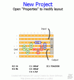
I have created a layout for a TDA2030 amplifier on a piece of stripboard. I was wondering if you all could take a look at it and see if there should be any changes made to it. It is the basic test setup shown in the datasheet.
http://home.planet.nl/~midde639/specs/tda2030.pdf
I have made a few assumptions with this that I will share with you:
1. The input is coming from a potentiometer setup as volume control
2. The output is going to a 1/4" jack for a guitar cabinet. The output zobel will be soldered to the 1/4" jack
3. C1 and C2 will probably take up more room then what is shown, but as I don't have the parts in front of me, I am not sure how much room they will take
4. I am aiming for +-18VDC supplies with an input signal of ~1.4V
5. R3, R2 and C4 form the feedback network
Anyways, what do you think?
Attachments
The Zobel network should be next to the IC.
Are you going to solder the 100 nF decoupling caps directly to the IC pins?
If you connect a guitar with an active pick-up, there could appear DC at the input. You should therefore use a DC blocking cap at the non-inverting input. That would mean to add C1 and R3 as per test circuit.
C4 is very small. The lowest note of an electric guitar is around 80 Hz, if I remember correctly. The corner frequency of that high-pass should be below a fifth of that frequency, i. e. the capacitor should be greater than or equal to 10 µF. Even bigger, if you use a DC blocking cap.
Does your guitar have enough output for a gain of only 10?
Thanks for the replys.
I will add the zobel on to the drawing after work. I was wondering about where I should put the decoupling caps. I will try to get them close to the chip. I will change C4 to 10uF as well.
I will be using a pre-amp with this and am expecting ~1.4V peak signal out of it. With a gain of 10, that should bring it up to 14V peak which I think will be good since I plan on using ~+-18VDC for the power supply.
I will be using a tone stack (Fender/Marshall style) near to the end of the pre-amp which will eliminating any dc offset so I planned on just connecting the volume pot directly into the non inverting input.
You will need space for the heatsink. How about soldering the decoupling caps directly to the IC pins from below the PCB?
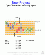
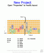
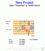
The feedback resistor should be as close as possible to the IC, which makes the second layout more promising (in theory).
The feedback resistor should be as close as possible to the IC, which makes the second layout more promising (in theory).
1875 on stripboard...
Did you build this in the end? If so, was it successful?
A couple of observations on the layout, your power ground track is quite a way from the chip, so those bypass caps under the board still have to span quite a distance? Also, your Zobel is grounded to signal ground, instinctively it feels like it should go to power ground as it supposed to provide a low impedance path at high frequencies.
I am interested in building an LM1875 on stripboard, but am naturally concerned about stability issues. I think I can handle the stripboard layout itself but have a few questions about giving the standard circuit the best stability I can. For reference, here is the typical application:
1. I want a lower gain, to use this as a PC amplifier without having the volume pot so near the end and hence poor stereo matching. Swapping R4 for 12K or mabye 16K will achieve this?
2. Quite often to maintain HF stability in an amplifier, the feedback resistor (R4) might be bypassed by a small value capacitor, to effectively lower the gain with increasing frequency. Is this applicable on the LM1875? How does 18pF sound for this application?
3. The Zobel is shown, I read it must be built as shown and near the output of the chip, not on the amplifier terminals. This is fine, would a 1.5R resistor also work here though, I have some on stock! Additionally, many amplifiers also include an output coil and resistor in parallel. Is this at all necessary on these chips?
4. I too will build with a signal and power ground on the stripboard. I will return these independently to a main star ground point. The speaker return ground shall connect directly to the main star ground. Alternatively, should I isolate the signal ground from the main ground by ~10R resistance, join them on the stripboard and make one return to the main star point? This is often done on discrete amplifiers.
5. The 2030 applications show the output clamping diodes (as seen in this thread too), the 1875 typical app does not show these. Are they required? Generally a sensible precaution?
Thanks for any input! 🙂
Did you build this in the end? If so, was it successful?
A couple of observations on the layout, your power ground track is quite a way from the chip, so those bypass caps under the board still have to span quite a distance? Also, your Zobel is grounded to signal ground, instinctively it feels like it should go to power ground as it supposed to provide a low impedance path at high frequencies.
I am interested in building an LM1875 on stripboard, but am naturally concerned about stability issues. I think I can handle the stripboard layout itself but have a few questions about giving the standard circuit the best stability I can. For reference, here is the typical application:
An externally hosted image should be here but it was not working when we last tested it.
1. I want a lower gain, to use this as a PC amplifier without having the volume pot so near the end and hence poor stereo matching. Swapping R4 for 12K or mabye 16K will achieve this?
2. Quite often to maintain HF stability in an amplifier, the feedback resistor (R4) might be bypassed by a small value capacitor, to effectively lower the gain with increasing frequency. Is this applicable on the LM1875? How does 18pF sound for this application?
3. The Zobel is shown, I read it must be built as shown and near the output of the chip, not on the amplifier terminals. This is fine, would a 1.5R resistor also work here though, I have some on stock! Additionally, many amplifiers also include an output coil and resistor in parallel. Is this at all necessary on these chips?
4. I too will build with a signal and power ground on the stripboard. I will return these independently to a main star ground point. The speaker return ground shall connect directly to the main star ground. Alternatively, should I isolate the signal ground from the main ground by ~10R resistance, join them on the stripboard and make one return to the main star point? This is often done on discrete amplifiers.
5. The 2030 applications show the output clamping diodes (as seen in this thread too), the 1875 typical app does not show these. Are they required? Generally a sensible precaution?
Thanks for any input! 🙂
Any suggestions at all? Looking at the stripboard, I barely have space for the standard layout. Which of the stability components I listed above would be considered most important? I can add the feedback loop capacitor if that would be advantageous? I could probably add an output coil at the amplifier speaker terminal itself if that were to be useful?
All protection components would depend on the nature of the load the amp is to drive. In general, inductive loads require the output clamping diodes and the Zobel. Capacitative loads require the coil. Most commercial amplifiers have at least one or more of these features. I use a LM3886 amplifier, and I use no protection due to benign cables and load. It hasn't blown up yet, though once a failed SMD capacitor did catch fire and vaporise the leads of a chip which still worked afterward.
I would try it with just a Zobel, as in the standard diagram. If the amp is unstable, you can add more protection later.
I would try it with just a Zobel, as in the standard diagram. If the amp is unstable, you can add more protection later.
Thanks for your response! I think it'll be quite a benign load, it's a small 8ohm fullrange driver, no crossover involved, only a notch filter. WinISD shows the driver in a cabinet with a lowest impedance point of 6ohms:
Safe to go ahead with the standard design? Cables will be very short, desktop application.
An externally hosted image should be here but it was not working when we last tested it.
Safe to go ahead with the standard design? Cables will be very short, desktop application.
Doesn't actually look too benign to me, the Zobel will be required and maybe the output coil as well. A benign load would look like this:
http://www.diyaudio.com/forums/multi-way/40570-impedance-eq-whats-good.html#post469839
The Zobel will help counter the effects of that steep rise above 3K, but not much you can do about those huge twin peaks... However sims are not usually very accurate, and it should work fine without killing the amplifier. I know the TDA 2030s are brutes, I had them running a 4ohm load in bridged configuration at somewhere near their 22V rail limits - they didn't sound too great but never burnt or blew, so I guess you'll be fine.
Thanks, so this is a capacitive load? I can add a coil around a 10R resistor on the output terminal quite easily if it'll help keep it under control. The diodes shouldn't be required?
No, the load is inductive above 3KHz. Impedance rise as frequency increases indicates inductive effects. Capacitative is exactly the other way around. This is why you need the Zobel, the Zobel has a decreasing impedance at high frequencies and compensates for the rising impedance, presenting a (theoretically) flat impedance to the driving amplifier.
You should be fine without the diodes, and the coil is to be added after the zobel, not before. Near the output terminal is fine. It could help if your speaker cables are capacitative.
You should be fine without the diodes, and the coil is to be added after the zobel, not before. Near the output terminal is fine. It could help if your speaker cables are capacitative.
Last edited:
I was thinking it would be inductive, which is why I wondered if the coil was applicable as it's a fix for capacitive loads? An output coil surely increases the effective output impedance of an amplifier at high frequencies, compounding the situation?
I'll definately want the Zobel, but are the diodes not required? I assume they prevent lockup of the chip's output stage due to voltages exceeding the rails. I couldn't see them integrated onto the chip's internal schematic, but perhaps the nature of the design makes them redundant?
Thanks again for your help!
This is kind of the limit of my theoretical knowledge and I may be wrong, but here goes:
Once the Zobel is in place, it should cancel out inductive effects of downstream speakers as well as the output coil. You need to select a needed turnover frequency (say 100-150KHz) and size the zobel accordingly, and the output coil will need to be sized similarly. When done properly, you should have an amp stable to a MHz or so no problem, and a flattish output impedance. The TDA2030 is not a very fast chip, so no further compensation should be needed. It is intrinsically bandwidth-restricted, but a Zobel with a lower frequency will stress the output needlessly.
The diodes are usually not needed at these power/voltage levels, as the design is limited by thermals and not junction breakdown of the output devices. For more powerful designs driving similar loads at higher voltages, diodes may have been useful. There is no harm in using them, but I personally don't, not for low-power chipamps. In theory, inductive loads may cause some issues which require clamping diodes so it's a good safety practice to have them in place. I believe (perhaps wrongly) that they affect sonics so I leave them out and take my chances 🙂
Ok, I think I will go ahead and build it as shown in the datasheet, but leave room on the board for the diodes. I will check the output while under the intended load (I have the proposed speaker load available to use) and decide if I need the diodes and/or output coil. Hopefully not though, it'll be used at about 1-2W output max in practise and with short speaker leads 🙂
Many thanks! I'll heat up my soldering iron 😀
Many thanks! I'll heat up my soldering iron 😀
- Status
- Not open for further replies.
- Home
- Amplifiers
- Chip Amps
- TDA2030 Stripboard Layout


