Hmmm...
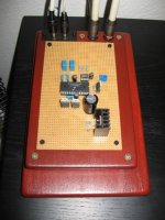
This DAC is my attempt to make design as simple as possible.
I have removed all caps I thought I won't need.Thats why I've used 5V supply.Minimal as possible.Something similar to 47Lab DAC.
I must say I like the sound of my DAC very much.
In near future I plan to build another DAC with cleaner supply
and active output stage.But no parallel dac chips - I didn't like how they sound in parallel.
Regards;
Igla
Say Zoran;
suppose you have 8V supply and say 2.2k I/V resistors.
Because of higher supply voltage you have more space to scale Rref before DAC starts clipping one or the other half of the signal.
Lets say Rref_1 is the lowest value and Rref_2 is the highest value before clipping.
Is there some difference in sound changing reference resistor from Rref_1 to Rref_2 ?
Regards;
Igla
Igla,
basicaly that is the experiance from the diy
members who get the measurements of dist.
against of values of Vref(Rvrev),
altouth the chips are different, good results
acheived with this values in very simple connection...
Anyway You can try with values of 1.2k to 1.6k for Rvref...
Plese note that simple IV with Riv only shifts the phase for 180deg...
With a lower values of Riv You could damage the dac chip like one of friend does...
Note the example of IV part from philips TDA1543 pdf datas, where Iref pin used differentlu from ther usual...
- Status
- This old topic is closed. If you want to reopen this topic, contact a moderator using the "Report Post" button.