Dear forum members,
Could you somebody explain please, how can I calculate the capacitance of the marked elements? It's not clearly visible what is above the capacitors. I see LPF, 49kHz (this sould be a cutoff freq., the 6dB/octave, and 1.2nF*8?)
What is the relation between its capacitance and the 680o Rout resistors? Is there any affect of the number of the DAC-IC? The capacitance should be different if I want to use 1 or 2 DAC-IC, instead of 4?
Thanks
Attachments
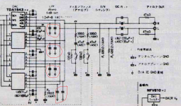
Neglecting the de-emphasis circuit and regarding the DC blocking caps as short circuits for signal frequencies:
On each line you have four paralleled 1.2 nF capacitors, 680 ohm, 47 kohm and whatever the resistance of the circuit connected to the outputs may be. Assuming that last one to be 10 kohm (guess), the cut-off frequency is:
f = 1/(2 pi RC) = 1/(2 pi (680 ohm // 47 kohm // 10 kohm)*(4 * 1.2 nF) ~= 52782 Hz
where // means the value of the parallel connection, so R1 // R2 // R3 = 1/(1/R1 + 1/R2 + 1/R3).
Assuming infinite input impedance of the next stage:
f = 1/(2 pi RC) = 1/(2 pi (680 ohm // 47 kohm)*(4 * 1.2 nF) ~= 49466 Hz
With fewer DAC ICs, you can either keep the resistances and the capacitances on each line the same (that is, keep 4.8 nF total from each line to ground) and accept that the output signal gets smaller, or you can scale up all resistances and scale down the filter capacitances. That is, use twice the resistance and half the capacitance with two DAC chips.
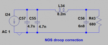
You could try using a CLC filter between your DAC and your I/V resistors. This can be tuned to give a rising response (reaching +3.2dB @ 20kHz) before rolling off to reduce the energy of images.
Could you help to suggest a design tool or expressions to calculate the correct values? Sorry but I'm mechanical engineer, so I don't have a deep knowledge about the electronics, but I want to learn it 😀
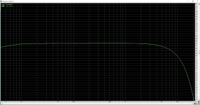
The drooping HF frequency response is to be expected from a NOS DAC with a crude output filter (or no output filter). Is that what you have?
Sorry but I'm mechanical engineer, so I don't have a deep knowledge about the electronics, but I want to learn it 😀
It may then be useful to know that LC filters, like the circuit arbraxalito posted, can be described with the same differential equations as mass-spring systems.
For an ideal linear capacitor, i = C dv/dt, where v is voltage, C capacitance, i current and t time.
For an ideal linear inductor, v = L di/dt, where L is inductance.
For an ideal linear resistor, v = R i, where R is resistance.
You know the mechanical equivalents better than I do.
Last edited:
- Status
- Not open for further replies.
- Home
- Source & Line
- Digital Line Level
- TDA1543 filter capacitor calculation