Koinichiwa,
As two hints. The old Philips Player is really up for good tweaking. I would not strip out the TDA1541 circuitry.
In fact, my current DAC uses the same chipset as your CDP.
See this discussion:
http://www.diyaudio.com/forums/showthread.php?s=&threadid=14605
I'd say sort the clock out, give the DAC nice clean supply lines with good quality Cap's, check what Decoupling Cap's are on the 14 pin's for that job (I have often ceramic SMD's!).
There once was a daugtherboard mod for such machines that allowed bigger size, high quality caps to be used. The TDA1541 is EXTREMELY sensitive to PSU quality and to the quality of these Cap's. Using a modest value (3u3 is good) Os-Con or NP Black gate on the two MSB Pins gives a bass slam and attack the TDA1543 stands no chance of ever matching. Higher up in the spectrum the TDA1541 sounds cleaner and clearer than either TDA1543 or 1545.
IF the TDA1541 is well optimised the TDA1543 (also pretty well optimiesed) sounds in comparison almost crude.
But yes, getting good sound from the TDA1543 requires a minimal PCB layout, one optimised PSU and no messing with DAC "continous calibration" decoupling Cap's. Getting the best from the TDA1541 requires a lot of work, three highly critical powersupplies, fourteen highly critical decoupling Cap's, an only minimal permiassable "parasitic" voltage from the I/V conversion circuitry and so on.
Yet if you already have the TDA1541 in place I'd say you'd be MAD swapping it for a 1543 or 1545. Simply optimise the Powersupplies, decoupling, clock and analogue stage and you have something that plays with most of the things out there, regardless of price.
And remember, electrolytic capacitors of more than 4 - 6 years age are a iability, terminate with extreme prejudice.
Sayonara
apassgear said:Peter, you sold me, I have ordered some 1543.
In the meanwhile I'll continue to play with the 1541, and then compare.
🙂 🙂 🙂
As two hints. The old Philips Player is really up for good tweaking. I would not strip out the TDA1541 circuitry.
In fact, my current DAC uses the same chipset as your CDP.
See this discussion:
http://www.diyaudio.com/forums/showthread.php?s=&threadid=14605
I'd say sort the clock out, give the DAC nice clean supply lines with good quality Cap's, check what Decoupling Cap's are on the 14 pin's for that job (I have often ceramic SMD's!).
There once was a daugtherboard mod for such machines that allowed bigger size, high quality caps to be used. The TDA1541 is EXTREMELY sensitive to PSU quality and to the quality of these Cap's. Using a modest value (3u3 is good) Os-Con or NP Black gate on the two MSB Pins gives a bass slam and attack the TDA1543 stands no chance of ever matching. Higher up in the spectrum the TDA1541 sounds cleaner and clearer than either TDA1543 or 1545.
IF the TDA1541 is well optimised the TDA1543 (also pretty well optimiesed) sounds in comparison almost crude.
But yes, getting good sound from the TDA1543 requires a minimal PCB layout, one optimised PSU and no messing with DAC "continous calibration" decoupling Cap's. Getting the best from the TDA1541 requires a lot of work, three highly critical powersupplies, fourteen highly critical decoupling Cap's, an only minimal permiassable "parasitic" voltage from the I/V conversion circuitry and so on.
Yet if you already have the TDA1541 in place I'd say you'd be MAD swapping it for a 1543 or 1545. Simply optimise the Powersupplies, decoupling, clock and analogue stage and you have something that plays with most of the things out there, regardless of price.
And remember, electrolytic capacitors of more than 4 - 6 years age are a iability, terminate with extreme prejudice.
Sayonara
Kuei is right, don't strip 1541 chip and don't do anything that won't allow you to go back to the original setup.
But the 1543 circuit, I propose, is so simple, that it can be added anytime, anywhere, and actually, I would be very interested in your impression on comparing those two DACs😉
I will also build TDA1541 DAC and see how it is.
But the 1543 circuit, I propose, is so simple, that it can be added anytime, anywhere, and actually, I would be very interested in your impression on comparing those two DACs😉
I will also build TDA1541 DAC and see how it is.
apassgear said:
The I/V is per Jung, if I remember this is a AD844 CF Opamp, but I'm not using a buffer so the signal goes directly from the I/V opamp stage through the output caps to the line amp.
Any suggestions???
Try Jocko´s circuit.
I replaced the analog output stage in my DAC (with AD844 as I-V converter) with a version of Jocko´s circuit .
It sounds better !
Look here:
Jocko´s simple I-V stage
Kuei,
Your input is appreciated.
The 14 bit decoupling caps are what Jung recommended on the Pooge series which are 1u poliprop conformals by Panasonic and do not have any small cap addition on the MSB, but will try the best I can find for the moment (no Oscon or BG at hand).
I have ordered some OPA627 and BUF634 (unfortunately OPA660 are out of stock) to make the I/V and buffer. I know you have given quite a number of alternatives for this stage but still I'm somewhat confused to the best alternative for this small player which only drives a 50K attenuator.
So sorry for asking again to point to a suitable I/V - buffer configutation schema. and the use of CCS with J-fet.
Peter,
I would be interest hearing from you on this 1541 vs 1543 shoot out.
We know we don't need to push you for those comments which are always welcomed.
I would be interest hearing from you on this 1541 vs 1543 shoot out.
We know we don't need to push you for those comments which are always welcomed.
Nicke,
I have looked to those JH stages but for some reason I shy away from discreet for this app.
Thanks all the same for your input, I'ts always nice to hear form others experiance.
I have looked to those JH stages but for some reason I shy away from discreet for this app.
Thanks all the same for your input, I'ts always nice to hear form others experiance.
Peter Daniel said:Here's the detail. The other two bypass caps are SMD, Y5U and X7R type, soldered directly to the pins underneath.
I would suggest to use 100k-200k resistors instead of the 47k drawn. And a better quality capacitor than Oscon for decoupling. Like the 100 uF BG FK (used in the Nonoz I&II). Maybe even panasonic FC would be ok there! I think that the BG would not need another smaller capacitor if the capacitor is placed very close to the DAC and regulator.
Anyone has some info for the best capacitor value for decoupling !? Kusunoki used 470 uF. Maybe for the regulators it's better to use a smaller cap ? Would 4.7 uF work !?
Fedde
Tony,
If you already have it, you can try AD844 in the configuration which Kuei proposed for OPA660.
Pedja
If you already have it, you can try AD844 in the configuration which Kuei proposed for OPA660.
Pedja
fedde said:
I would suggest to use 100k-200k resistors instead of the 47k drawn. And a better quality capacitor than Oscon for decoupling. Like the 100 uF BG FK (used in the Nonoz I&II). Maybe even panasonic FC would be ok there! I think that the BG would not need another smaller capacitor if the capacitor is placed very close to the DAC and regulator.
Anyone has some info for the best capacitor value for decoupling !? Kusunoki used 470 uF. Maybe for the regulators it's better to use a smaller cap ? Would 4.7 uF work !?
Fedde
Actually, there was a whole thread about decoupling caps and the famous triplets. Those SMD caps are very important and the values I chosen were recommended by Pete Goudreau. Here's the exact caps: 120u Panasonic HFQ, AVX 0612 270n Z5U, AVX 0612 10n X7R.
I used 33u Nichcon as it was what I had at hand, but will use something bigger next time. Also, Ksunoki in his first DAC used 33u for decoupling at ea chip.
What is the difference when 100k-200k resistors are used at the output?
they will put less load on the dacs output, there only purpose is to short any voltage stored in the cap to ground when the dac is not attached to anything.
/micke
/micke
well you could but if you disconect the dac while on you will here some hevy pops when conecting it again...
/micke
/micke
I guess one way to avoid it would be installing relays that short the output to ground when switched off and providing delay when switching on.
That would work. Or you use a large resistor 100-500 k. But you get two problems then:
- the DC of the unconnected output is not exactly zero (with 100 k the DC is quite small). Well, it is wise anyway to turn down the volume of the amp while connecting...
- you get some extra resistor noise. I think this is not a big problem
Fedde
- the DC of the unconnected output is not exactly zero (with 100 k the DC is quite small). Well, it is wise anyway to turn down the volume of the amp while connecting...
- you get some extra resistor noise. I think this is not a big problem
Fedde
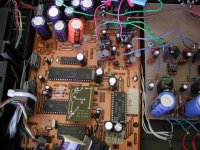
After this long absence let me summarize what I've done to the CDP.
After changing all decoupling caps (all bypassed with small film caps) I changed all the PSU caps, taking Kuei's advice.
Al caps were "NOS" Panasonic HFS (even though I do have HFQ's) with the exception of the 6800u located before the +5V reg which was replaced by two regular ELNAs 4700u 50V for a measured 10Ku.
Other changes made were the replacement of 2 resitors at each of the I/V Opamps from Roderstain to CGW non magnetics MF.
Also I added the 3.3u caps at the MSB (Panasonic HFS). Plus some ferrite beads to the output of the Jung regs and a big split ferrite to all wires coming and going between the servo and main boards.
I have logged about 8/10 hours of break-in so still not fully done plus sone 15 hours on.
My impresions so far is that is very clean sounding, deep and quite wide sundstage with lots of detail, concert music puts a huge crowd behind the performers nice bass and cleaner highs far exceeding what I have heard up to date (not much though). In relation to my Delta Sigma (DS) wins in all counts by an ample marging but two.
Dynamics and HF drama or energy.
To follow my quest and see what much is available I am preparing an Opamp I/V to replace my old stage.
The new one will be done with LM6181 (single LM6182) using a standard schem.
I have also ordered OPA660 to try Kuei's proposal.
In the other hand I'm also finishing a separate PSU (actualy 2) to feed the DAC with the three voltages needed.
Some pics of the PSU.
Attachments

I've just started building my TDA1543 design using Peter Daniels schematic on post #14. I am using a 33uF Blackgate N, SCR 10uF and Hovland 0.022uF for bypassing. All resistors are Vishay and both 4.7uF caps are Blackgate N types! This should be nice!
Thanks for the design - I'll let you know how it goes!
Gaz
Thanks for the design - I'll let you know how it goes!
Gaz
Pics of my CD-PRO2 PSU and TDA1543 DAC / PSU are here...
http://www.diyaudio.com/forums/showthread.php?postid=208535#post208535
Enjoy!
Gaz
http://www.diyaudio.com/forums/showthread.php?postid=208535#post208535
Enjoy!
Gaz
- Status
- Not open for further replies.
- Home
- Source & Line
- Digital Source
- TDA1541A S1 come back!!!