Dear all.
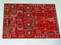
this is the coming version II of the twins 1541a DAc.
photos shows is the tube buffer first.
This is the test print of the new tube buffer.
improvement as about.
1. added the battery bias for 6c45/6dj8 SRPP.
2. increase one more socket that can use EZ80,81,WE412a & 6x4 tube.
3. all the circuit coated high purity silver one the copper surface for high speed signal transfer. The solder contact point still use gold paint.
thx
thomas
Attachments
Dear all,
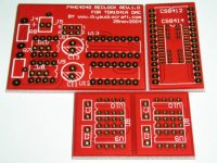
pls see the reclock PCB special for the tda1541a use.
I choose 74HC4040 for the reclock.
This PCB will extra 2 small PCBs. one is the smd (cs8414 etc) change to DIP.
Another small pcb is for single OP-amp change to Dual op-amp.
Than diyers can less some time to enjoy more diy's interest.
Not need to care the parts was SMD or DIP, single or dual op-amp.........
thx
thomas
Attachments
Hello
I've just discovered this thread.
A TDA1541A at a higher rate using an ASRC upsampler like the SRC4192 are someting I would like to try using the parts of my NOS TDA1541A board.
I've done a schematic of it, I would use a DIR9001 and with a SRC4192 bypass switch and an external clock.
Is my schematic are ok ?
Any suggestions ?
Thank you
Bye
Gaetan
Attachments
Last edited:
Hello
I've seen a small error on my schematic on the SRC4192 pins for output data format, for a 16 bits output data, the pins OWL1 and OWL0 should be high, so they are now connected to the +3.3v
Here I included the correction in this new schematic image.
I did not include I/V amp in the schematic but there would be a low pass filter in the I/V amp.
Thank
Bye
Gaetan
Attachments

Last edited:
Hello
Anyone can check my schematic shown in post #24 ?
Is my schematic would work ok ?
Is there any errors in my schematic ?
Thank
Bye
Gaetan
Anyone can check my schematic shown in post #24 ?
Is my schematic would work ok ?
Is there any errors in my schematic ?
Thank
Bye
Gaetan
Last edited:
- Status
- Not open for further replies.