More on my dual 1541a Rainbow_hui dac saga..
This has now been configured for differential working using a pair of Sowter 9545 transformers in MK1 test version.
Using one dac for normal and the other for inverted data operation meant just interposing a spare inverter in IC11 - a 74HC14 before pin3 of dac 2.
To prove that I had connected the transformers correctly, with both dacs receiving the same data, there was no ouput ( as good as!) as expected.
Next step is to use the dacs in simultaneous mode with one dac per channel. However this requires 2s complement to offset binary conversion and a simple method of doing so has been devised which I hope to test next week.
In the meantime more listening to be done for the consequences of the lsb error due to inverting the data. (Nothing audible with a quick listen)
I found a mistake on the pcb, the unused gates of IC11 are shown correctly as having the inputs tied to ground except that its actually pin 6 (output) that was grounded instead of pin 5.
Ianj
One way is to use a DF (like PMD100) and put the tda's in simulatious mode. There are designs on the net with a cpld to do this also (but with i2s feeds iirc).
One way is to use a DF (like PMD100) and put the tda's in simulatious mode. There are designs on the net with a cpld to do this also (but with i2s feeds iirc).
It only needs the msb inverting so doesn't seem a difficult job with a some 74F logic..
The data stream is msb first, and commences after ws goes high so we know where it is and 'lasts' for one bck cycle....
(I am running the dacs in nos mode and want to keep everything as simple as possible so that would rule out a PMD100)
Ianj
Interesting project, I have something similar in my mind, but the many gates needed for a perfect I2S inverter (like the one designed by Pedja Rogic) deterred me. If you succeeded, please share it with us. I would like to combine a dual differential TDA1541A DAC with my tansformer/tube I/V converter...
http://www.diyaudio.com/forums/digi...s-valve-output-stage-lundahl-transformer.html
http://www.diyaudio.com/forums/digi...s-valve-output-stage-lundahl-transformer.html
Interesting project, I have something similar in my mind, but the many gates needed for a perfect I2S inverter (like the one designed by Pedja Rogic) deterred me. If you succeeded, please share it with us. I would like to combine a dual differential TDA1541A DAC with my tansformer/tube I/V converter...
http://www.diyaudio.com/forums/digi...s-valve-output-stage-lundahl-transformer.html
Why not try the simple method I am currently evaluating of just inverting the data to one dac? (assuming they are currently paralled)
I have been listening to my favourite cds for several hours and cannot hear any unwanted side effects.
I am in fact surprised with how clean the results are, with no digital noise, aliasing, nor other artifacts considering that there is no filtering at all (apart from that afforded by the transformers) and nos mode is being used. Its not perfect and not a major advance over parallel dacs but more work is planned.
The lsb errors resulting from imperfect inversion surely do not matter because when a track is playing there is always enough noise in the recording* to swamp the errors?
I'll let my ears be the judge everytime rather than pursue perfection & theory.
*from the mics, mixers, audience, performers and general ambient noise, air conditioning etc etc.
Progress so far..
This is a summary of the mods and I/v transformer connection to the raindrop_hui dual dac pcb. I have taken a holistc approach and modded the preamp input as well.
a) One DAC receives inverted data using a spare inverter in U11 (74hc14) i.e. its one dac for true and one for inverted data. There are no other mods to the I2S signals.
b) All four dac outputs are loaded with .1% Beyslag 100R resistors.
c)The 9545 transmformer primaries are connected between the true and inverted dac outputs. The centre tap is not connected to ground, this prevents any dc flowing through the transformer due to the dac output offset. (I cannot hear any difference when I do ground it)
d) The CD input of the Quad 34 has been modified by removal of the input coupling cap, and series 39k resistor, just leaving a 1M resistor from non inverting input to ground.
The results are excellent but the next step made a surprising difference...
e) The secondary of the transformers (series connected) were loaded with 2.7K at the preamp input socket. This is reflected to the primary as about 90r and had a very surprising effect on improving the 3 dimensionality and depth and also boosting the low end a little at the expense of a drop in signal. This isn't a problem as the Quad 34 Cd input is very sensitive compared to modern standards (100mv).
Until I get round to trying the one dac per channel configuation its hard to know whether this will produce an even better result. Maybe the extra complexity of the logic needed to process the I2S signals will cancel out any gains....
Next I will increase some of the decoupling caps - all are 100n currently.
The result so far is superior to my MF X-dac. (an X-ray player supplies the spdif input)
SCOPE TRACES
I dug out an unused TC Electronics M350 audio effects processor which I remembered has an spdif output. The inputs were fed from a sig gen and the bypass butotn pressed.
The resulting 1Khz square wave suffers from plenty of ringing (taken from the M350 analogue output).
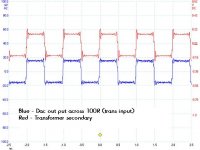
The final traces were with the transformer connected between the dac L & -L outputs, in parallel with 100R (no resistors to ground on the dac output. The centre tap was grounded and the secondary loaded with 47k.
The previous traces were with 100R to ground on all dac outputs and the secondary loaded with 2K, centre tap not grounded.
image 1 shows the dac outputs - dac 2 is the inverting dac.
image 2 shows input and output of the transformer
image 3 shows analogue output of the M350 v output of the transformer.
I dug out an unused TC Electronics M350 audio effects processor which I remembered has an spdif output. The inputs were fed from a sig gen and the bypass butotn pressed.
The resulting 1Khz square wave suffers from plenty of ringing (taken from the M350 analogue output).
The final traces were with the transformer connected between the dac L & -L outputs, in parallel with 100R (no resistors to ground on the dac output. The centre tap was grounded and the secondary loaded with 47k.
The previous traces were with 100R to ground on all dac outputs and the secondary loaded with 2K, centre tap not grounded.
image 1 shows the dac outputs - dac 2 is the inverting dac.
image 2 shows input and output of the transformer
image 3 shows analogue output of the M350 v output of the transformer.
Attachments


More listening tests
Its often said that the TDA1541 does not like dc on its outputs and so needs a very low load value load resistor ege 15 to 33r. However I can find no mention of this on the 1991 datasheet.
Well using Sowters 9545 transformers, and dropping down from 100r to 47r produces a much less pleasant sound. It is thinner, harsher and flatter.
I have put up with this all week to see if I can find any merit at all in using a lower resistor and then today, switched back to 100r resistors.
The result is more bass, greater dimensionality and depth, and lack of harshness, yet no lack of treble. If anything it is clearer and more delicate. A vast improvement on the lower value.
My next step is to interpose EC Designs common gate fet (2sk170) I/V converters between dacs and transformer. The common gate configuration offers very low input impedance, unity current gain and with a 500r drain resistor, an output signal of 2vp-p (from the 4ma dac output current).
However the output impedance is highish so I'm not sure what the audible result will be. The transformers are connected between the true and inverted dac outputs with the centre tap not grounded so no dc flows through the windings. I will no doubt need to experiment with the secondary load resistors which are currently 2k7. The preamp's (Quad34) input opamp was also changed from a OPA2604 to a NE5532.
Sorry for the off-topic post but why would anyone with diy abilities use something as profoundly awful as a Quad 34?
Sorry for the off-topic post but why would anyone with diy abilities use something as profoundly awful as a Quad 34?
Please keep your off-topic opinions to yourself.
I've been using the dual differential TDA1541 nos dac for a couple of years now, with the Sowter 9545 I/v transformers and no other filtering.
However I spotted a Sabre dac pcb on Ebay - item no 291641644046
Its the Es9023 version (ie not the top of the Sabre range dac) with I2S input and for £15 I thought I'd compare it to the TDA dac.
The socket on the TDA dac pcb vacated by the SAA7220 has the I2S signals on pins 1,2,3 and 0 & 5v on pins 12 and 24 so it could not have been easier to connect it and leaves the TDA dac still working.
I connected the outputs to my passive preamp to do some A-B listening tests.
Once again, the old TDA1541 out shone the Sabre dac, though not by much. The sound was a little fuller bodied and with more space around the instruments. The Sabre dac sounded as though the mics had been moved closer to the instruments but although there wasn't a massive difference I kept switching back to the old dac.
I've also compared this with an Audio Note Dac 1 (AD1865) and I still prefer the TDA1541 sound to this as well.
If I needed a dac for a wide range of digital sources a Sabre dac would be my choice, but for CDs, I'll stick with the TDA1541 dac - there is something special about the TDA1541 sound that takes some beating!
UPDATED PCB
I am working on a few minor mods to my original dual differential 1541 pcb consisting of:
On board regulators moved close to the pcb edge to allow for the fitting of heatsinks. (I use low noise 78xx type from ldovr.com)
Revised ground traces with separate digital, analogue and psu grounds.
Inductor between the regulator ouputs and dacs.
Jumper to change from simultaneous to 2s complement so the dacs can be differential or parallel.
Possibly fit UFL connector pads for the digital inputs.
The design has no SMD components and has no onboard I/V.
Uses 100uf Nichicon UKL series ultra low leakage dem decoupling capacitors.
Optional jumper to synchronise the dem clocks.
Both dem clock pins are available for external reclocking.
This time you should do it right, that is, one single nonoversampling 44/16 DAC, no external DEM reclocking, no voltage regulators, but bulky polypropylene decoupling capacitors.
Your definition of 'right' differs from mine.
2 dacs, differential (simultaneous mode, clock stopped after data latched,) I/V by Sowter transformer with I/V resistor across the secondaries. No other filtering needed, and no current injection to cancel the output offset current required.
I2S is 3.3v from Ian Canada's I2S to PCM board, + clock board + FIFO II so no supply rail bounce. Perhaps I'll try elevating the 0v to these to prevent ground bounce.
The 2nd I2S input is for a USB-I2S interface (a few £s from ebay)
I am going to use LifePo4 cells instead of main psu.

Just to let you all know: AliXpress currently has SAA7220 boards sporting a CPLD that creates simultaneous balanced signals to the TDA1541. Haven't connected it yet, it is under $20....
The only way to get rid of an average sound with this great dac chip is to go with a great front-end and bestly with the said simultaneous mode and give away all those filters chips made by Philips in that days.
One board comes in mind : the JLSOUNDS Lab usb/spidf to I2S or Sim mode. I2S to PCM fro Iancanada can easily handles a sim symetric tda1541A design but its timing scheme is less good than the JLSounds. Cables system are not exactly the same and all of that counts in the final sound ou can acheive. Pick your prefered poison...
A classic PSU a is as great as LiPo cells as far as the traffos are C-Core and you use a fast linear reg. LiPo cells can winn if you don't use regs... which will be hard as you need two x 5 to 6V max on two rails... the 15V can run at 16V iirc but not 16,5V -5x 3.3V Lipo-, although the volatge falls fastly to 3.2V by cell which sends you to 16V for the -15V rail of the TDA1541A, but it will not work for the two others rails.And as soon as you use regs between lipo and a load... the cells loose all the interest.
Then comes the problem of the whole layout, objectivly few have it all : Audial pcbs, ECDESIGNS of the TDA1541A days...some more expensive stuffs as well but at crazy prices: AMR, etc.
For the DEM caps, it is known and readable here in some threads that inductance of the 14 DEM caps must be short and that the dielectric has also its word in the sound : sms acrylic/PEN caps from Panasonic or Cornell Dublier have the academic palms at that job. SilverMica or folded styren or non etalized KP Wima for the standalone DEM timing cap.
Good Luck 🙂
Last edited:
I've driven the TDA1541A from an JLSounds board in differential. Not the sound that I prefer from the TDA. I actually do enjoy the SAA7220 sound signature...
- Home
- Source & Line
- Digital Line Level
- TDA1541A Dual differential MK1