Hi all,
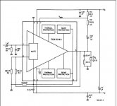
I'm building a active 2+1 system with 3xTDA1514A in next week. I will apply the Philips's original circuit which shown in TDA1514 datasheet. But i have a question and i cannot find an answer in that datasheet. I can see the mute/stby input is pin 3 and its referenced to pin4 (-Vcc). But in this figure pin 3 connected to pin 2 and pin 2 looks like the SOAR circuit's output (or something else). I want to add a stand-by and a mute switch to my circuit. What i'm gonna do? How can i add that switches?
Thanks a lot for any helps.
Attachments
Yea, i know that circuit already. But where is the mute/stby connection? You dont recommend TDA1514A but i have four of that chip! And i paid 11€ each.. So i have to use them.
Anyway... Thanks a lot for your interests Abidr.. But i need a mute/stdby circuit for it.
Anyway... Thanks a lot for your interests Abidr.. But i need a mute/stdby circuit for it.
Dx i ll look at it tomorrow morning do drop me an email, i ll email u and not post here. and this chip costs only about 3$ here, so does 3886 and 7294 so its better off with them rather than this piece of junk by phillips.. Although sound quality is very good but it keeps getting fried up for no reason at all and in return destroys the spreakers as well.
When connecting the power, pin 3 is at -Vp, then is charging through R 470K.
The circuit has 3 modes, depending of the U3, probably refering to -Vp:
U3 < 1V ==> stand-by
U3 = 2-4.5V ==> mute
U3 > 5V ==> run.
I built 3 amplifiers with TDA1514, Only one of them had problems, heatsink got very hot, but after improper use (2 ohm speaker, maximum power, etc.). After this "adventure", amplifier never worked as before. Always got hot. Problably it is realy a problem with this chip, because is no longer produced.
- Status
- Not open for further replies.