Hi hope someone can help my understanding here. I am repairing a Cambridge Audio A1 mk3 fitted with two tda1514a chip amps. The two rail fuses were blown so I powered up through a DIM bulb tester. It indicated a problem (bright 100w bulb). I removed the two chips and found one had significant low ohms between supply pins and others. The other channel did not have shorts. I put the suspected good chip back in circuit and powered up. All ok this time with current draw and fuses but I checked the dc offset voltage across the single channel speaker output. Bearing in mind only one chip in circuit which I didn’t think should matter, I am getting 2.3vdc at speaker terminal. I haven’t tried speakers yet but this doesn’t appear correct. Am I missing anything in my understanding or do you think the second chip has an issue also.
Many thanks
Mark
Many thanks
Mark
Taken at face value your 2.3 volts shows a problem as there should always be minimal DC voltage present across the speaker output.
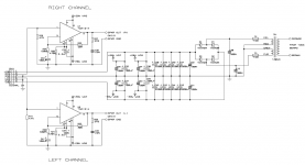
I'm assuming this is a DC coupled circuit running on split rails rather than a single rail design with output coupling cap in which case some voltage would be expected with no load present.
I'm assuming this is a DC coupled circuit running on split rails rather than a single rail design with output coupling cap in which case some voltage would be expected with no load present.
Hi and thanks for responding. Yes split rail as in the attached. My gut said that there was something wrong with the second chip despite not causing fuse blow itself. I have not connected speakers as precaution whilst everything checks out. One chip gone the second giving the 2+ Vdc at speaker terminals. Just wondered if there was anything peculiar about tda1514a which would show this. Very simple and tda1514a spec sheet states low output offset!!!
Attachments
That's a pretty standard circuit. Any DC offset should be very low and certainly under -/+ 50 mv DC.
What is odd is that failure of one chip is a common and expected scenario but one that should have zero impact on the other channel. As long as the supplies are correct the chip should produce a very low offset.
It might be worth just connecting a dummy load to this channel and seeing if the offset remains. Even a 100 ohm resistor would suffice.
On remote possibility is the chip is unstable with no load but if that were so then it would be bad design.
Check C41. And the voltages on pin 1 and 9. Those should be zero. The TDA1514 is just a powerful opamp.
Thanks I will try that. I have 2 chips on order but just trying to further my knowledge and understanding. I will try the 100R load. and retest/report back.
OK thanks guys. C42 100uF checks out ok (101.2uf and Vloss 0.7% and esr 0.27Ohm)
Pin 1 Ov to gnd Pin 9 2.6v to gnd. Voltage across 1 and 9 2.6v
When 100R load placed across speaker output, 2.6vdc remains !
Pin 1 Ov to gnd Pin 9 2.6v to gnd. Voltage across 1 and 9 2.6v
When 100R load placed across speaker output, 2.6vdc remains !
It would be worth just measuring the DC voltage on pin 1 which is the input. This should be zero.
That only leaves the chip then really... or its oscillating and unstable and so skewing the reading a DVM shows, or...
If the unit has a hidden history then things like spillage or contamination from say a leaky cap could conceivably cause issues. It would have to be around the chip though.
All a bit of a coincidence really, to have a definite fault like a zapped chip and to then also have a weird issue on the other channel.
Thanks so much for your help. Agree with the thinking. Board very clean and no other real clues. Voltage regs for smaller control op amps check out ok also. Have checked all electrolytics around the chip and found ok. Ah well I will await 2 new chips and get them in to try. I will report back for the benefit of others.
You're welcome 🙂
The chip should obey all the classic rules applicable to an opamp... namely that the output will do whatever it takes to bring the voltage difference between the two inputs to 'zero'. Looking like the chip then at this point.
The chip should obey all the classic rules applicable to an opamp... namely that the output will do whatever it takes to bring the voltage difference between the two inputs to 'zero'. Looking like the chip then at this point.
2 new chips received and installed. Powered up through dim bulb rig. No current issues, output dc offset now down at a few millivolts per channel. Connected up to speakers and a lovely sound was had.
It pays to be questioning and cautious.
Thank you for the helping hand guys.
Mark
It pays to be questioning and cautious.
Thank you for the helping hand guys.
Mark
 that's good. Pleased to hear it was an easy fix in the end.
I'd simply replace the amp chips, and as Mooly said, load a 100 ohm resistor to each, dim-bulb it, and if everything checks out, call it a day.
- Home
- Amplifiers
- Chip Amps
- Tda 1514a help please