Hi everyone.
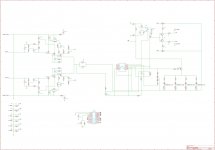
Finally I managed to reverse-engineer the pre-phono board.
I have attached an image of the schematics.
Maybe there are some errors...
This page contains some suggestions for better performances.
Now some questions on the matter.
1) He suggest to bypass the caps near the output (C6 C7 C18 C19 in the schematics). What if I want to get rid of all the MUTE circuit? I'm not interested to put the preamp in standby using SW1. Do you guys think that it's possible to do it?
2) Translated from the page:
I figured out that they may be C5 & C24 and C12 & C23, even if there are no 10mF caps on the board... (Most likely a typo) Am I right? What about changing the value from 10uF & 4.7uF to 2.2uF?
3) Translated from the page:
Comments, advices and suggestions are very welcome.
Thanks
So long
S.
Finally I managed to reverse-engineer the pre-phono board.
I have attached an image of the schematics.
Maybe there are some errors...
This page contains some suggestions for better performances.
Now some questions on the matter.
1) He suggest to bypass the caps near the output (C6 C7 C18 C19 in the schematics). What if I want to get rid of all the MUTE circuit? I'm not interested to put the preamp in standby using SW1. Do you guys think that it's possible to do it?
2) Translated from the page:
Another important modification is the substitution of the phono section input and output capacitors (10mf 50v (sic) and 4.7uF 25V) with some metallized polypropylene 2.2uF
I figured out that they may be C5 & C24 and C12 & C23, even if there are no 10mF caps on the board... (Most likely a typo) Am I right? What about changing the value from 10uF & 4.7uF to 2.2uF?
3) Translated from the page:
Is it worth all the trouble (and the cost)?To complete the work I've substituted various electrolytics with liquid tantalum capacitors, bypassed some others with polyester of bigger capacitance and substituted the RIAA capacitors with some silver-mica
Comments, advices and suggestions are very welcome.
Thanks
So long
S.
Attachments
- Status
- Not open for further replies.