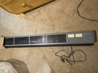
Hey all. I recently picked up a TASCAM MU-2632 meter bridge unit. It’s an old unit and I can’t find much info on the meter bridge specifically online, but it looks like it was used with the M-2600 MK2: https://reverb.com/item/29128921-tas...24-meterbridge
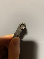
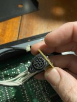
It looks like it uses 8-pin mini DIN connections (I’m not really that experienced with DIN connections) that provide signal to each of the visual meters.
Is there any way that I can add this to my VERY basic home studio setup? It would probably really just be more decorative than anything, but I wondered if there was a way to take an L-R 1/4” Jack signal and somehow get those into the unit to watch the lights dance?
Attachments
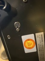
Is that DIN connector the only external port on the unit? If so that suggests the communications between the mixer and meter bridge are serial in nature as there simply aren't enough pins to send 24 +2 channels individually. If that is the case then it's unlikely you can get any meter action without the matching mixer.
Ok, great. So then do you think if I get a couple of F 8 pin DIN > RCA adapters, and then a couple of RCA > 1/4” jack adapters that would work? Seems like 8 pin DIN connectors all have double L+R RCA connectors, but then how would a stereo signal work with a single meter? Or perhaps I get 2 DIN > RCA and just use one channel from each to two of the meters… I’m just thinking out loud.
But do you think either of those solutions would work?
But do you think either of those solutions would work?
This is where it gets interesting, what are you using as the signal input to this thing?
I suspect it won't take much signal level to drive these meters so you probably don't need the main outputs of a mixing console for example... maybe a line level signal like the record outputs... just millivolts not volts.
Then you have to probe the DIN connector pins with that signal or use a generated test signal to figure out what makes the needle move and go from there. I would suspect there are 2 pins to provide power for the back lighting and then 2 more pins that supply sig and ground for the meter, and the rest of the pins in that connector are potentially unused.
I figured I would use the line outputs from an audio interface, 1 and 2 as L and R, as the main outputs would be sending to my amp> monitor speakers.
The unit comes with a power supply plug so I assumed that would power the lighting. Sorry I should have mentioned that before as well.
How would I go about probing the DIN connector pins with a signal? Sorry, I’m a complete electrical novice, but I’m looking to learn so all of this is good for me.
The unit comes with a power supply plug so I assumed that would power the lighting. Sorry I should have mentioned that before as well.
How would I go about probing the DIN connector pins with a signal? Sorry, I’m a complete electrical novice, but I’m looking to learn so all of this is good for me.
as this stuff was created and used pre internet era, there's very little info uploaded to be found....so that leaves us with old school methods like meter probing and or physically dissembling it and tracing the connections to the circuit board to simply get an idea of what goes where.
i would just do a quick "disturbance test" of the pins in the connector to see which and if any segments deflect/show....
with that many pins some could be range selections.
i would just do a quick "disturbance test" of the pins in the connector to see which and if any segments deflect/show....
with that many pins some could be range selections.
Well at least through my ignorance we’re creating a trail for people in future!
So, with that in mind (apologies again for my ignorance, imagine you’re describing it to a 12 year old: which isn’t that far from my actual experience) - when you say a “disturbance test”, I can’t find much info online for exactly how to do that. I’m not sure exactly how to go about that - is it just a case of using a multimeter at each end of the cables that came with it? Or do I buy those connecting cables/adapters and checking the signals on the end of the unplugged DIN cable?
Thanks for your patience!
sorry that's a real old school term coined by a guy named Jack Darr.
simply using a small wire or a meter probe and touching the pins (no ground necessary) should hopefully introduce enough noise to see some meter deflection it's akin to the "disturbance test" for whether or not an amp on the bench is passing signal i.e. touching an open Rca to see if it produces audible hum in the speaker.
with a meter it is possible to get more insight as to what's what but still fastest is a physical disassembly and trace out....it gives you a chance to clean out some dust and cobwebs as well.
by the way do you own a meter?
ah so we are going to be teaching some basics we are ....ok....first would be just looking for grounds so low ohms with the power "off" of course!!
any chance you could upload more pics of just how many din connectors there are?
if you open it up and get a few pics of it's innards we could decipher this faster!
any chance you could upload more pics of just how many din connectors there are?
if you open it up and get a few pics of it's innards we could decipher this faster!
Last edited:
Sorry, I’ve been out of town for a week.
Ok, I will have time over the weekend to do some investigation and I can open it up and see what we’ve got going on.
And yes - I’m a complete novice and very appreciative of your patience and advice! I’m very excited to learn, - we never really did anything interesting in physics class back in high school, so while I aced the subject, we never really got to do anything practical, so it’s an area I just never pursued.
Coming back to making music again after a long break of numerous years, and with some time on my hands, I’m really enthusiastic about picking up some skills and seeing what I can do. I’d love to build some guitar effects, preamps, practical little projects and just know how to fix things. I hate how there’s so much electronic waste we generate and I love older, unique pieces of equipment.
It’s all a little intimidating but with sites like this and Reddit, finding different communities for support and guidance is incredible to me.
I’ll post this weekend with some pictures!
Apologies for delay, life stuff.
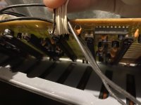
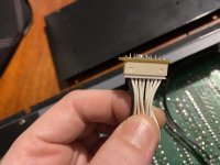
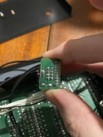
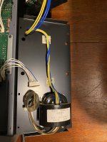
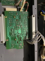
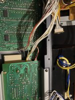
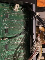
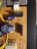
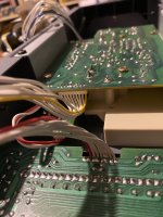
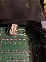
So I had an opportunity to open the strip up this evening, and I’m unsure of how useful these will be. All but one of the wires connected to each DIN connector is white, with one being black. Images attached. Let me know thoughts on how to progress next and I’ll do some more inspection!
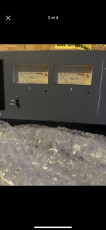
Oh, there are 5 DIN connectors, one per meter x 4, and 1 for the two (L and R) VU meters.
So I had an opportunity to open the strip up this evening, and I’m unsure of how useful these will be. All but one of the wires connected to each DIN connector is white, with one being black. Images attached. Let me know thoughts on how to progress next and I’ll do some more inspection!
Oh, there are 5 DIN connectors, one per meter x 4, and 1 for the two (L and R) VU meters.
Attachments
-
 60E80099-1AC1-4DBA-8000-269F54DB3292.jpeg327.7 KB · Views: 8
 -
 A58A99B5-50B0-44E3-AE70-047009D629C3.jpeg484.6 KB · Views: 11
 -
 D6587843-C828-4ECA-BB5F-9F29438C7D1E.jpeg336 KB · Views: 14
 -
 25401550-3104-4C56-9B6E-FFE9F1DC7F74.jpeg746.6 KB · Views: 12
 -
 50604C7F-F582-4E75-A03D-67336AF0D978.jpeg355.1 KB · Views: 10
 -
 F8299B7A-1D0C-4350-81F4-AB45DDADBC04.jpeg364.5 KB · Views: 13
 -
 8498F890-AC7C-47E4-99C0-4EB5026BA5C8.jpeg605.9 KB · Views: 9
 -
 2CC869DF-7FFE-4C97-86C7-8B8231A8A645.jpeg406.2 KB · Views: 12
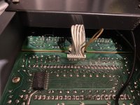
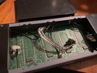
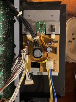
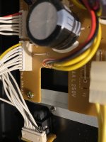
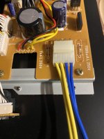
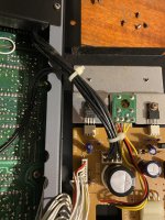
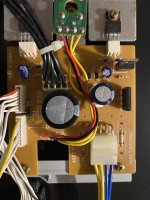
I decided to open the end with the VU meters as well as that’s where the power supply comes in. Turns out there’s also a circuit that sits in section 2 (I guess I’m numbering from power supply/VU meters being 1).
Attachments
-
 7EB8A1D9-6B0F-4636-AA2E-78E6F7A589C3.jpeg591.7 KB · Views: 12
 -
 995BE92B-5BE2-4109-BF2B-83A3EC68896D.jpeg579 KB · Views: 13
 -
 0F9C4998-62B3-4B94-961C-F830B6C7D611.jpeg586.3 KB · Views: 12
 -
 A71C14A6-83A7-4950-AC65-9219DF2B36FB.jpeg530.7 KB · Views: 11
 -
 09A7ADE4-87C7-4285-BE84-CF330B67EC8B.jpeg693.3 KB · Views: 14
 -
 96E05C0D-F938-48C8-95F9-84A70C454AA7.jpeg383 KB · Views: 12
 -
 20ADF47E-3FCC-4735-A106-E37D5AADAF27.jpeg406.6 KB · Views: 11
 -
 3A5F3318-F1BE-4F32-B70D-F3B02CB9F6D3.jpeg389.6 KB · Views: 9
 -
 5A1BEDB1-562E-4C74-866B-F782151ABE2E.jpeg358.2 KB · Views: 11
 -
 8993EA4E-A2EE-4FD6-9BF8-8ECFD3C67E3F.jpeg432.9 KB · Views: 10
 -
 BAA63B7D-EE15-499F-B1C8-D069056CACC9.jpeg524.2 KB · Views: 10
 -
 7ACFD739-A697-4891-8174-4E45C4B78031.jpeg416.8 KB · Views: 11
 -
 7BA3D1C1-9842-4873-A75C-4D791C9F5ED9.jpeg423.9 KB · Views: 8
so it appears that each din carries 8 channels and a ground.
just how many din connectors in total (i would assume 4 to cover 32 channels in total)?
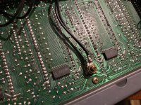
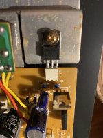
just what are the chip numbers?
with it appearing to not power on , have you insured that all connectors are place and no loose components or boards are shorting?
Last edited:
- Home
- Live Sound
- PA Systems
- Tascam M2600 Meter Bridge (MU-2632)