Hello everyone
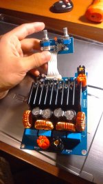
I just bought a yianjing tas5630 1x600w subwoofer amp board, as in the picture.
This one: 600w /4ohm TAS5630 + OPA1632DR + TL072 Class D Digital Subwoofer Amplifier Board | eBay
However, I cant make it to make any sound at all.
Obviously, the +50V par is for power (connected to a 100w 48V source). I guess BASS+/- is the speaker output, and the audio source goes to the input pins, but no matter how I connect them, it doesn't work. How do even these 3 pins work? I had not seen them before
Anyone got any clues?
Attachments
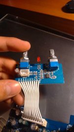
How do even these 3 pins work? I had not seen them before.
If this is for stereo source, it could be to add the L+R for mono.
If it's a balanced input, two of the pins could be for a balanced mono signal.
Hard to tell which it is from the photo. I'd guess L+R input.
Last edited:
Yes, looking at a similar amp the pins are R-GND-L...
TAS5630 (600W) subwoofer machine/home audio amplifer machine | eBay
There doesn't appear to be any sort of standby or mute function, so it looks like it should start singing as soon and you supply power and input signal.
TAS5630 (600W) subwoofer machine/home audio amplifer machine | eBay
There doesn't appear to be any sort of standby or mute function, so it looks like it should start singing as soon and you supply power and input signal.
Yes, looking at a similar amp the pins are R-GND-L.
See if the center pin is ground with an ohm meter. Then try L and R into the other two pins.
That preamp thing sums the signals from L and R to a mono signal.
So it doesn't matter to how you connect it, as long as you use the center pin for ground.
There are some small holes right in front of the heatsink.
The silk screen says 'btl' and 'pbtl'.
I think you must connect each center pin with the one that says 'pbtl' next o it, to make it operate.
I don't have my board at hand, so i can not 100% surely say how i have done it on mine.
Better check the traces and compare it to the datasheet.
Thanks guys, but this wasn't just an input problem.
I measured the voltage from a 100hz sine tone coming from my pc at 0.8V (don't know if it's RMS or peak to peak or whatever, just that there are 0,8V).
Then, I connected this wave to the input board, which was supposedly wired to a TL072 op amp. I checked the voltage out from the preamp and going to the main board at 2.3V, and it responded to both the volume knob and the tone one (50-150hz). That means that the op amp is working.
As I can confirm that the sine wave is actually going onto the main board, the only explanations left are that either the sine wave isn't ever reaching the main amp, or that the main amp's output path is disconnected somewhere before the speaker outputs. Either one is far beyond my knowledge and capabilities to fix it, so I'm guessing that I'll need a refund, or a new one.
Any thoughts?
is it possible to bypass the pre-amp thingy and connect L or R directly to the amp, to use 1x 600W for full range purpose?
Well, as the pre amp board has 12V, ground and OUT pins, I guess connecting directly the input to ground and out should do the trick.is it possible to bypass the pre-amp thingy and connect L or R directly to the amp, to use 1x 600W for full range purpose?
I have no way to confirm this, tho, as mine won't do anything
Read my previous posting carefully.
I'm 100% sure, but i think you must close those jumpers in front of the heatsink.
Otherwise the signal path towards the chip input is not closed.
I think it is possible to feed the signal directly into those spots where the jumpers are meant to sit.
But in that case you would bypass the OPA1632 which creates differential signal onboard.
And that means you have to connect one (or two) of those spots to ground.
All i wrote has to be taken with a grain of salt, because i do not have my board at hand and cannot check any traces.
Hi Buehgemeiste,
I read your post 🙂
I didn't understand it correctly I think.
I would have the put a jumper on the PBTL pins and then have to connect my input signal to the GND and OUT input (where normally the signal from the preamp is going into) on the main amp board.
Is there any gain switches on this amp board?
There is no gain switch on this board.
Add pins and jumpers to those holes next to the heatsink.
The silk screen should explain how to use the jumpers.
The preamp isn't too bad, so there is nothing wrong with using it for a subwoofer.
If you need to omit the preamp you can find out which of the pins carries the signal:
Check whichpin is connected to the center pin of the volume pot on the preamp.
Then you can feed the signal to that pin.
It is possible to this amp act in stereo btl mode.
But i cannot show you pictures and i have no time to guide you.
Make it work, explore what you need and how it can be achieved.
Ok, so I was looking which 2.0 board I should buy. On aliexpress I see 2 different desings (if I look at opamps). There arr the ones with opa1632dr and the ones with ad827. Which one would be better?
I had the same problem some time ago. Without touching the quality of the DAC,
studied the photo and see that version with ad827 preamp has a 50V capacitors.
Its little confuse me, it is almost at the limit of the nominal voltage value. Maybe if you psu will give lower then nominal V values, its a acceptable. But from perfect-considerations i prefer version with 63 or 100V caps, to improve reliability, as i hope.
Other normal way, if 827 DAC is better, is to change caps to big nominals, or not afraid of it, and so will work in current config.. some time))
- Status
- Not open for further replies.
- Home
- Amplifiers
- Class D
- TAS5630 question