Hi,
I'm looking at this amp here, from Sinewave Electronics:
4CHANNEL 1200W DUAL TAS5630 High Field CLASS D Amp V1.1
It has two TAS5630 amps, which can produce either 4x300W / 4Ω, or 2x600W / 2Ω.
Does this mean the amp can be bridged to produce more power when configured for two channels, and if so, will it be stable at 8Ω loads? I'm wondering why it says 2x600W / 2Ω specifically.
Many questions - can someone please enlighten me a bit on the subject?
Thanks
The amplifier, as a single chip, is already configured as a bridged device, but it depends on how you are using it.
First of all it can be used as a 4 channel amplifier (single ended, SE). In this configuration it is single ended and large DC coupling caps are required in the signal path to block the DC offset that the outputs are biased to. This really isn't the way the amplifier was intended to be used, but it can be, so offers an extra degree of flexibility.
The second mode is with it used as a stereo amplifier. Conceptually this is virtually the same as the standard bridging of a normal amplifier (bridged tied load, or BTL). Two of the four channels are used per channel of amplification with one channel driven inverted to its counter part. One of the four channels is then the 'hot' channel and one the 'cold'. Both channels sit at the same DC potential that the signal channel above did, but as both terminals of the loudspeaker are driven to the same potential, no current flows and no DC blocking caps are required. You also end up with double the voltage swing.
This is how the amplifier was designed to be used. A single supply rail, half biasing the output stages, used bridged to remove the need for coupling caps whilst still providing a good output voltage swing. It also allows the use of TIs carrier cancelling technology the BD modulation scheme.
The third configuration is basically the same as the two channel mode except that the two, bridged, stereo outputs, are wired in parallel with one another (parallel bridged tied load, PBTL). As the amplifier is already bridged you don't gain any advantage in terms of voltage swing, so its output power into an 8 ohm load is exactly the same. The amplifier can now simply output double the current. This enables it to drive more troublesome loads a lot more easily, but unless you need the current, there is virtually no reason to go with the bridged version.
The above amplifier basically has two TAS5630 chips configured as PBTL when operating as 2x600W. It is perfectly capable of driving 8 ohm loads, but you wont see any power increase vs it configured as 4x300.
The reason why it says 2 ohms is because you need to connect a 2 ohm load to it to actually see it deliver 600 watts. If you attach a 4 ohm load to it, it will only provide 300 watts.
The only reason why I would go with a 2xPBTL implementation is if your loudspeakers are a pain to drive. That is they might say 'nominal 8 ohms', but have an impedance minimum of 3 ohms with a phase angle of 45 degrees or so.
One thing to bear in mind here is that you need one heck of a power supply to actually take advantage of the PBTL implementation, in that you need the 50v supply rail to remain rock solid and not droop under load. If the PSU droops under load then this will inherently limit the current delivery anyway.
Thanks a lot for this detailed reply - clears everything up! So basically the amp has the same voltage swing in BTL and PBTL mode, but PBTL gives the ability to draw more current, and thus drive tougher loads.
About the power supply, I'm looking at powering the amp with four 12V SLA batteries in series. These types of batteries should be capable of delivering the adequate amount of amps, if I'm not mistaken.
About the power supply, I'm looking at powering the amp with four 12V SLA batteries in series. These types of batteries should be capable of delivering the adequate amount of amps, if I'm not mistaken.
Yes they should hopefully be capable but do make sure that they are specified to do so.
The amplifier itself internally limits at 19amps, this is per channel, so in PBTL mode can demand a tremendous amount of instantaneous current. I am not sure how lead acid batteries respond to transient current demands.
The amplifier itself internally limits at 19amps, this is per channel, so in PBTL mode can demand a tremendous amount of instantaneous current. I am not sure how lead acid batteries respond to transient current demands.
You are right that not all SLA batteries are equal, and can have different intended applications.
I'm also investigating in placing some big caps across the battery terminals in order to help with transient current. I don't know yet what capacitance they should have.
I'm also investigating in placing some big caps across the battery terminals in order to help with transient current. I don't know yet what capacitance they should have.
TAS4200 4 CHANNEL MODULE HAVE VERY GOOD S/N
Hello!Everyone,
Thanks for your concern!
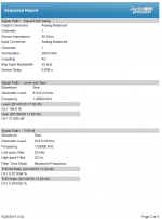
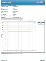
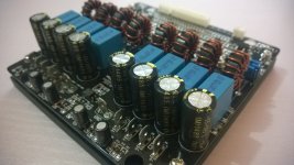
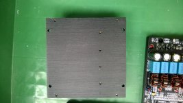
This four channel module have new 4 balance input version now, attach some photos and AP test result here.
this module have very good Signal to Noise Ratio, above 100dB, sound should very clear now.
Some addtional circuit to make tas chip more stable than orginal version.
Hello!Everyone,
Thanks for your concern!
This four channel module have new 4 balance input version now, attach some photos and AP test result here.
this module have very good Signal to Noise Ratio, above 100dB, sound should very clear now.
Some addtional circuit to make tas chip more stable than orginal version.
Attachments

- Status
- Not open for further replies.
- Home
- Amplifiers
- Class D
- TAS5630 - Can it be bridged?