I purchased one of these last summer: Assembled TAS5611 digital amplifier board class D (125W + 125W) | eBay
I finally got around to using it a couple of weeks ago. I use it to drive two Panasonic Turbo Thruster speakers with sound from my HDTV. It enhances the sound from the TVs built-in speakers and also aids in stereo separation. I am powering it with a Meanwell EPS-65S 36 volt power supply adjusted down to 32 volts.
I put the amplifier and power supply in a salvaged DVD player case. I did not want to modify the looks of the case. I used the RCA jacks on the back for audio in and speaker out connections. I wanted to use the front panel push buttton to turn the amp on and off. Since the button is not a latching type, I designed a J-K flip flop circuit to toggle a relay to turn the amp on and off. But I had a problem with the relay contacts welding together due to the large value electrolytics on the power supply rails. I could have gone to a larger relay and solved that problem. However, the flip flop circuit wasn't 100% reliable.
Another issue was the amplifier had a problem with audio pops on power up and power down. I decided to solve the relay problem and pop problem with a new design. I used a PIC10F322 to control the power on and off sequence. I used a pair of IRF5305 Mosfets to switch power for the amplifer and preamp. That solved the relay contact welding problem. The power up pop problem is solved by holding the amplifier reset pin low until the output stages are up and running. On power down, I activate the reset pin before removing power from the amplifier and preamp stages. After a sufficient delay, I release the reset pin. Both power up and power down are absolutely silent.
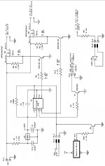
Attached is a jpg of the circuit. The Chinese amplifier apparently duplicates the suggested circuit from the TI data sheet for the TAS5611. That diagram shows a 100 ohm resistor connected to a Reset terminal. The other end of the resistor connects to pin 2 on the TAS5611. Pin 2 also has a 47K ohm resistor connected to VREG. I soldered a wire to the Reset terminal side of the 100 ohm resistor and connected it to PL4 on my schematic. The 100 ohm and 47K ohm resistors are on the bottom of the circuit board so they are easy to access. There isn't an actual Reset terminal on the board. The 100 ohm resistor doesn't connect to anything. Just solder a wire to that end of the resistor.
On my schematic you will see LED1. This is the front panel LED that was on the DVD player case. I connected it through a 2.2K ohm resistor to the 12 volt line on my preamp board. When power is applied to the preamp, it lights the LED to indicate the amplifier is powered on.
One other thing I did was add a simple circuit so I could turn the amp on and off with a remote keyfob unit. I used the transmitter(1095) and receiver(1096) from Adafruit for this purpose. The receiver D4 terminal connects to R20 on my schematic. This corresponds to button A on the transmitter. They have the buttons and outputs reversed on the units, i.e., button A is D4 and button D is D0.
One thing to note about the circuit, and this applies to all amplifiers. The audio source needs to be connected and turned on before powering the amplifier on or off. If the amplifier is already on and you power up the source, you will get a pop or thump. The same thing applies to powering the source off with the amplifier still powered on, pop or thump will happen.
If anyone is interested in the source code or hex code, just let me know and I can post a zip file of it here. The software was developed using MPLAB X, v3.45 and the free XC8 compiler. The circuit could also be used with other TI amps such as the TPA3251 that use a similar reset circuit. The Mosfets are rated at 55 volts and 31 amps so they can handle large loads.
I finally got around to using it a couple of weeks ago. I use it to drive two Panasonic Turbo Thruster speakers with sound from my HDTV. It enhances the sound from the TVs built-in speakers and also aids in stereo separation. I am powering it with a Meanwell EPS-65S 36 volt power supply adjusted down to 32 volts.
I put the amplifier and power supply in a salvaged DVD player case. I did not want to modify the looks of the case. I used the RCA jacks on the back for audio in and speaker out connections. I wanted to use the front panel push buttton to turn the amp on and off. Since the button is not a latching type, I designed a J-K flip flop circuit to toggle a relay to turn the amp on and off. But I had a problem with the relay contacts welding together due to the large value electrolytics on the power supply rails. I could have gone to a larger relay and solved that problem. However, the flip flop circuit wasn't 100% reliable.
Another issue was the amplifier had a problem with audio pops on power up and power down. I decided to solve the relay problem and pop problem with a new design. I used a PIC10F322 to control the power on and off sequence. I used a pair of IRF5305 Mosfets to switch power for the amplifer and preamp. That solved the relay contact welding problem. The power up pop problem is solved by holding the amplifier reset pin low until the output stages are up and running. On power down, I activate the reset pin before removing power from the amplifier and preamp stages. After a sufficient delay, I release the reset pin. Both power up and power down are absolutely silent.
Attached is a jpg of the circuit. The Chinese amplifier apparently duplicates the suggested circuit from the TI data sheet for the TAS5611. That diagram shows a 100 ohm resistor connected to a Reset terminal. The other end of the resistor connects to pin 2 on the TAS5611. Pin 2 also has a 47K ohm resistor connected to VREG. I soldered a wire to the Reset terminal side of the 100 ohm resistor and connected it to PL4 on my schematic. The 100 ohm and 47K ohm resistors are on the bottom of the circuit board so they are easy to access. There isn't an actual Reset terminal on the board. The 100 ohm resistor doesn't connect to anything. Just solder a wire to that end of the resistor.
On my schematic you will see LED1. This is the front panel LED that was on the DVD player case. I connected it through a 2.2K ohm resistor to the 12 volt line on my preamp board. When power is applied to the preamp, it lights the LED to indicate the amplifier is powered on.
One other thing I did was add a simple circuit so I could turn the amp on and off with a remote keyfob unit. I used the transmitter(1095) and receiver(1096) from Adafruit for this purpose. The receiver D4 terminal connects to R20 on my schematic. This corresponds to button A on the transmitter. They have the buttons and outputs reversed on the units, i.e., button A is D4 and button D is D0.
One thing to note about the circuit, and this applies to all amplifiers. The audio source needs to be connected and turned on before powering the amplifier on or off. If the amplifier is already on and you power up the source, you will get a pop or thump. The same thing applies to powering the source off with the amplifier still powered on, pop or thump will happen.
If anyone is interested in the source code or hex code, just let me know and I can post a zip file of it here. The software was developed using MPLAB X, v3.45 and the free XC8 compiler. The circuit could also be used with other TI amps such as the TPA3251 that use a similar reset circuit. The Mosfets are rated at 55 volts and 31 amps so they can handle large loads.
Attachments
It would be handy if you publish the rest please. GPL licensed source code + hex bin. Thanks muchly. Useful to have available.
cacao,
The main.c and main.h code is attached. Since it is for an older Microchip part, you should be able to create a project in the old MPLAB-8x or newer MPLAB X IDE. The code is well commented so it should be easy to understand how it operates.
The main.c and main.h code is attached. Since it is for an older Microchip part, you should be able to create a project in the old MPLAB-8x or newer MPLAB X IDE. The code is well commented so it should be easy to understand how it operates.
Attachments
- Status
- Not open for further replies.