Good day,
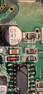
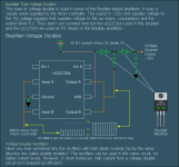
Anyone happen to know what diode was in place at location D6? It was completely melted out of the amp when I got it. The MJD32C burned the pad up pretty good.
Thanks in advance!
Anyone happen to know what diode was in place at location D6? It was completely melted out of the amp when I got it. The MJD32C burned the pad up pretty good.
Thanks in advance!
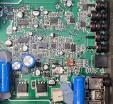
Attachments

Last edited:
Posssibly:
https://www.diodes.com/datasheet/download/US1M.pdf
You could email Taramps to get a definitive answer.
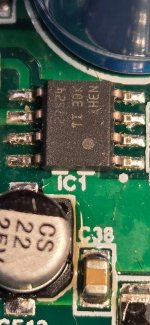
Did IC1 fail as well?
https://www.diodes.com/datasheet/download/US1M.pdf
You could email Taramps to get a definitive answer.
Did IC1 fail as well?
Ok, I'll try messaging them.
The original problem, a wire strand grounded an output transistor tab to the case.
I'm not certain about IC1. I still have a short between gate and source of all the output pads on one side of the amp. I removed IC12, 13, and 14 and now IC 1. The short is still there. Also R105 is smoked. I think it is supposed to be 1 ohm.
Attachments
Is there an R41 feeding the other driver IC?
Do all FETs read 0.0 ohms gate to source? or is it only one reading that low per bank?
Do all FETs read 0.0 ohms gate to source? or is it only one reading that low per bank?
Yes, R41 is 1 ohm. So, safe to assume R105 is also. It does look like 1R0 when I look closely at it.
Half of them (2 per bank, 4 total of 8) were shorted. I was wrong. I now only read little over 10 ohms. Likely reading the gate values at this point.
I need to order some parts. I'll come back to this when they're in.
Thanks Perry.
Half of them (2 per bank, 4 total of 8) were shorted. I was wrong. I now only read little over 10 ohms. Likely reading the gate values at this point.
I need to order some parts. I'll come back to this when they're in.
Thanks Perry.
Good afternoon,
Ok. Current condition of this amp. Repopulated everything damaged that I've found so far. Including replacing all the damaged diodes, resistors and zeners in the bad channel. Everything matches the other side.
IC1 seems OK. Output side has nice 7v square waves. Where do those go? Couldn't find them elsewhere....
The power supply transistors. I do get switching. They seem to be ok, just removed to not have the rail voltage. All output transistors are removed.
With remote applied, the fans turn on momentarily. Both IR20957S have 10.3v on pin 1, nothing on Pin 2, Pin 3 has switching, Pin 10 has 0.00v and Pin 14 has 4.50v.
Is there a way to get them to send drive to the output gate pads? Should I just put in the power supply transistors?
Attachments

Good day sir. It's definitely boosting the square wave between 2 to 7 and 4 to 5. There are currently no outputs or ps transistors in circuit.
Which IC did you want those readings from Perry?
Which IC did you want those readings from Perry?
IR20957S
Those are the supply terminals and need voltage for the IC to function. They all have different reference points, the reason for the placement of the black probe.
Those are the supply terminals and need voltage for the IC to function. They all have different reference points, the reason for the placement of the black probe.
4-2 should be above 70% of the 4-1 voltage. It could be low because the high-side is in UVLO (under voltage lockout). Are both ICs at approximately the same voltage 13-15?
I have not reinstalled the ps transistors yet. There does seem to be as much as 4.7v of rail on the output pads. No outputs in either.
Should I reinstall the power supply transistors?
Should I reinstall the power supply transistors?
Install enough to get rail voltage.
Do you have output FETs in stock? They don't have to be the exact replacement part, something with a sufficient voltage rating should work, initially.
There aren't many things I can say I hate but these ICs are at the top of the list.
Do you have output FETs in stock? They don't have to be the exact replacement part, something with a sufficient voltage rating should work, initially.
There aren't many things I can say I hate but these ICs are at the top of the list.
Ok, will do.
I replaced the IC on the one side. As well as the 511s. I have the original set of outputs from the good side and plenty of stock of the originals new. They are just IRFB4115s.
I replaced the IC on the one side. As well as the 511s. I have the original set of outputs from the good side and plenty of stock of the originals new. They are just IRFB4115s.
There are ways to get them to produce pulses without the output FETs but it's sometimes easier to install enough parts (survivors are perfectly fine) to get them to power up normally. Then if there are problems, you can deal with it in a different way.
I put in some ps and output transistors. Everything looks good. Nothing is heating up. Going to add the rest, put in case and do some testing. Thanks sir!
- Home
- General Interest
- Car Audio
- Taramps Smart 5 Bass