Taramps HD 8000
I have a Taramps HD 8000_R2 1 ohm version that had a blown power supply that I have repaired. The problem now is that the amplifier powers up with only B+ and ground connected and NO remote voltage connected.
When I connect remote voltage to the amp, the amp shuts down.
Any ideas what this could be. I haven’t encountered this before on a Taramps.
Thanks,
David
That sounds odd but I don't know these amps. Follow the remote line in and look for the first (2 generally) transistors that you come to.
I get 1.5 volts DC on the remote terminal and line with just B+ and ground connected. I replaced IC4 (voltage regulator on the daughter board for the digital display because the remote line right there and those regulators have been used in remote turn on circuits in other Taramps. I checked all of the SMD components on the daughter board. They all check within tolerance. That’s the work I did on the bottom of the board. This is the first actual component that the remote line sees in the circuit. Up until this point it is just trace line.
At the exact same location on the top side of the board the remote circuit sees some other components. I’ll explain what I did on the top side with another post.
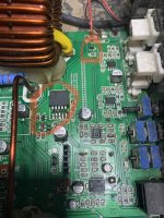
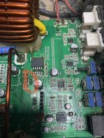
Here is a picture of the area of interest on the bottom of the board.
At the exact same location on the top side of the board the remote circuit sees some other components. I’ll explain what I did on the top side with another post.
Here is a picture of the area of interest on the bottom of the board.
Attachments
On the top side of the board the first components the remote line sees is a LL4148 diode (I replaced it). Then Q6 is a BJT (BC817) and I replaced it. Then a few resistors and caps that all test within tolerance the a linear regulator LM2941CSX (I replaced it) and according to one schematic I have Q7 (BC087) is also connected to the remote line for the fans but it connects into the collector of the BJT Q6. I replaced Q7. I’m still seeing the same problem.
Nothing has changed.
I’m not sure what or how some voltage is bleeding over into the remote circuit. I checked all of the op amps. They all have the necessary +-15 volts and none were low. So I don’t think any of them are shorted.
David
Nothing has changed.
I’m not sure what or how some voltage is bleeding over into the remote circuit. I checked all of the op amps. They all have the necessary +-15 volts and none were low. So I don’t think any of them are shorted.
David
Attachments
Last edited:
Someone with experience may be more helpful. The suggestion I made was purely generic for most remote circuits,
R92 reads 33.12k ohms In circuit. It is marked 3302 so that checks out.
Pin 2 voltage of the LM2941 with only B+ and ground connected is 0.025 volts.
Pin 2 voltage of the LM2941 with only B+ and ground connected is 0.025 volts.
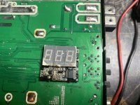
Ok. Figured out the problem. The three pins circled in the picture connect to the digital display. Top pin is power, the second pin from top is remote, and the bottom pin is ground. The trace around the ground pin connecting it to the main board was damaged on the top side. I exposed so if the ground plane and reconnected the ground pin with some wire and solder.
Works like it should now. Thanks for the help everyone.
David
Works like it should now. Thanks for the help everyone.
David
Attachments
Dont know what you mean with 087, but Q7 is BC817 which is driven by PIC to enable fan spin and not connected anyhow to remote line.I have Q7 (BC087) is also connected to the remote line for the fans but it connects into the collector of the BJT Q6. I replaced Q7. I’m still seeing the same problem.
David
R92 act as a pull up resistor. LM2941 being turned off when is driven high and turned ON when driven low. You must understand why pin 2 of LM2941is being pulled down by transistor Q6.
If 10K R96 is removed of the circuit - amp wont turn on?
Update: while i was writing the post, you already figured out. Good!
Last edited:
- Home
- General Interest
- Car Audio
- Taramps HD 8000 remote turn on circuit