Okay.
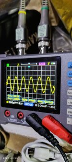
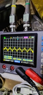
Channel 1/3 have stronger pulses than 2/4.
Also every few seconds there's this huge pulse down to negative.
Channel 1/3 have stronger pulses than 2/4.
Also every few seconds there's this huge pulse down to negative.
With all semiconductors clamped tightly to the heatsink...
If you touch a load (dummy or high-power speaker) to channels 3 and 4 (one at a time) does one pulse more strongly than the other?
Do you have audio with essentially no DC on the input terminals of the IC?
If you touch a load (dummy or high-power speaker) to channels 3 and 4 (one at a time) does one pulse more strongly than the other?
Do you have audio with essentially no DC on the input terminals of the IC?
I'm going to attach the board back to the heatsink and test with the speakers and an input 1K sine wave.
Sorry about the delay Perry took more time putting the amp together and getting the input than I thought.
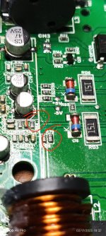
In the attach image those 2 resistor has the signal input on them. On the side that's coming from the op-amp is the nice looking 1K sine wave, but on the side going to the IC is the weird looking sine wave.
Also channels 1 and 3 has a loud popping sound periodically. But no sound and on the terminals that the speakers are connected to there's no voltage.
Attachments
The distortion isn't unexpected. When the IC is functioning normally, there may be absolutely no audio visible there unless the IC is driven into clipping.
You have 4 high-side FETs and 4 low-side FETs. With no power applied and the rail caps discharged, measure the resistance from:
Pin numbers on the FETs:
1-2
1-3
2-3
Do this for all FETs then reverse the probes and repeat. Do this for all FETs, comparing the readings for all corresponding FETs (high-side or low-side). Do all corresponding FETs read approximately the same?
Okay, as you instructed. I measured each high side and low side MOSFET from each channel.
Channels 1-2 high and low side FETs pins 1-2 = 3+M Ohms when reversed 1.9 M Ohms, the same goes for pins 1-3. But when I probe pins 2-3 it's like 100+ ohms and when I reverse the the probes it's a dead short then it starts to climb. It's the same for both the high and low side FETs for channels 1-2.
On channels 3-4, pins 1-2 and 1-3 measures the same 3+M Ohms and 1.9M ohms in reverse, but pins 2-3 measures 1+K ohms both ways. And this goes for the high and low side FETs.
Now that it's been powered down for a while, see if the way the ch1 and 2 read 2-3 now read the same as ch3 and 4.
I was trying to find something that corresponded to the channels causing the problem but it didn't show with the initial readings.
Set your meter to diode-check and check all FETs 2-3. Check one way then reverse the probes. Do all read essentially the same?
I was trying to find something that corresponded to the channels causing the problem but it didn't show with the initial readings.
Set your meter to diode-check and check all FETs 2-3. Check one way then reverse the probes. Do all read essentially the same?
Okay.
So the low readings from channels 1-2 is not an issue?
So I checked all FETs, on channels 1-2 pins 2-3 measures low then starts to climb and in the reverse it measures 000.0 then starts to climb after a few seconds.
On channels 3-4 1.4 volts goes up to 2+ volts, on the reverse it just measures as a normal MOSFET .400+ volts.
I have no idea! I thought you would be able to shed some light on it. What was i checking for?
The readings on channels 1-2 pins 2-3 just seems off. What could could cause that? Maybe whatever it is could be causing the IC from starting up? And is there anything else i need to check for? Also the diodes and resistors that make up the circuit for the 5+ and 5- are quite warm, and the op-amps too and the IC itself. Could there be a short or a component that only shows up bad when power is going through it.
The readings on channels 1-2 pins 2-3 just seems off. What could could cause that? Maybe whatever it is could be causing the IC from starting up? And is there anything else i need to check for? Also the diodes and resistors that make up the circuit for the 5+ and 5- are quite warm, and the op-amps too and the IC itself. Could there be a short or a component that only shows up bad when power is going through it.
There are a lot of other components that could affect the readings.
Pull the two that you don't read diodes on and check them out of the circuit.
With these ICs you sometimes have to look for inconsistencies to find the problem.
The resistors in some of these amps are fed from the rails and dissipate enough power for them to run hot. Are the resistors tiny little 0805s or are they large 1w types?
What's the supply for the op-amps? I thought you said it was ±14v. Am I mistaken?
And also cause this effect.
I checked them out of circuit prior, they all read fine.
And the only inconsistency I see at the moment is the fluctuating CSD voltage.
It's the large 1 watt SMD resistors that are connected directly to the +14/-14 rails.
Yes there's +14/-14 on the op-amps.
I'm at a lost, where do I go from here?
The diodes and resistors measure fine that make up the circuitry for the IC, so maybe the caps are bad, one of the ceramics or maybe one of the electrolytic? Or there could be a bad resistor that I'm not reading? The resistors that are attached to pins 33-35 could they be at fault? Or the caps, diodes and resistors that makes up the bootstrap circuit?
Last edited:
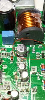
This resistor 01D, which is a 100K, it measures the 100K or close to but then drops back down to like 70K and then goes back up again. Also the CSD what voltage should it be exactly?
That resistor is connected to the op-amp output on the top side, which also goes off to the ceramic cap on the left. Then the other side goes off to one of the pins on The IC.
That resistor is connected to the op-amp output on the top side, which also goes off to the ceramic cap on the left. Then the other side goes off to one of the pins on The IC.
Attachments
These ICs and others like the 2092 and the 20957 have an internal (on-board) over-current circuit and they won't allow the IC to start if there is a problem. They also have under-voltage protection but you said the IC had 14v on the VCC terminal. Was that 14v with reference to the negative power supply rail or referenced to ground?
What components do you see connected to the CSD terminal?
The CSD determines the mode of the IC and can act as an input or an output. That means it can be controlled internally or externally. If you can find the circuit connected to it, externally and disconnect it, that should tell you whether the protect is coming from the IC or externally.
Is this IC, after you replaced it behaving the same as it was when it was originally installed?
Oh I see, yes the 14V is referenced to the negative supply.
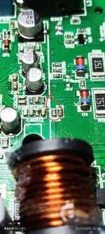
Circled is what's connected to PIN 48 when the empty pads are shorted there's no CSD voltage.
How would know if the protection is coming from the IC or external? Because the amp is still on when the pads are shorted. With the IC de-soldering the amp LED comes on for a bit and then goes out, but it's also trying to pull more than 1 amp.
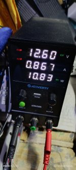
My PS is set to 12.6 volts 1 amp, just trying to not blow up anything. But with the IC out, the voltage drops down to 7 volts and the amp is trying to pull more than 1 amp.
Circled is what's connected to PIN 48 when the empty pads are shorted there's no CSD voltage.
How would know if the protection is coming from the IC or external? Because the amp is still on when the pads are shorted. With the IC de-soldering the amp LED comes on for a bit and then goes out, but it's also trying to pull more than 1 amp.
My PS is set to 12.6 volts 1 amp, just trying to not blow up anything. But with the IC out, the voltage drops down to 7 volts and the amp is trying to pull more than 1 amp.
Attachments
Yes the new IC is behaving the same as the original.These ICs and others like the 2092 and the 20957 have an internal (on-board) over-current circuit and they won't allow the IC to start if there is a problem. They also have under-voltage protection but you said the IC had 14v on the VCC terminal. Was that 14v with reference to the negative power supply rail or referenced to ground?
What components do you see connected to the CSD terminal?
The CSD determines the mode of the IC and can act as an input or an output. That means it can be controlled internally or externally. If you can find the circuit connected to it, externally and disconnect it, that should tell you whether the protect is coming from the IC or externally.
Is this IC, after you replaced it behaving the same as it was when it was originally installed?
You may simply be starving the amp for current. Clamp everything down tightly and set the supply higher. At least 5 amps. I'd go to full current (10 amps?) and just watch for excessive current that lasts more than about 1 second.
The high current draw with no IC could have been because there are no pulldown resistors on the gates of the output FETs (guessing).
The high current draw with no IC could have been because there are no pulldown resistors on the gates of the output FETs (guessing).
Okay, I bumped it up to 5A when it started up it didn't pull much more than 1A, then settles at .8A.
I think that's what it is too for the excess current pull when the IC is out.
What's next?
Could it be because the IC doesn't have active cooling? But then again, where is the CSD voltage supposed to be?
I think that's what it is too for the excess current pull when the IC is out.
What's next?
Could it be because the IC doesn't have active cooling? But then again, where is the CSD voltage supposed to be?
Attachments
- Home
- General Interest
- Car Audio
- Taramps DS 1200X4 2 ohms turns on but no audio