X
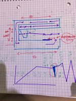
Lol’!!!!! 80 cm in each fold (3 off the front, one off the rear. 240/80. Drivers enter at 0349 for that individual pipe at each initial segment/fold/start).Just what we need, a schizophrenic Karlson variation! 😱
Attachments
Last edited:
OK, thanks! But why the need to "drop in mass loading restrictions between outputs"? Is HR really that far off or........?
Oops, That’s the purple plate with the red arrow next to it to move back-and-forth to try to fix what you see in the impedancepot and response in a Paraflethat’s the purple plate with the red arrow next to it to move back-and-forth to try to fix what you see in the impendance plot and response in a Paraflex. And doing that it works fine but you’re choking it out at some point it really does sound good but so could a smaller speaker with the same output likely…OK, thanks! But why the need to "drop in mass loading restrictions between outputs"? Is HR really that far off or........?
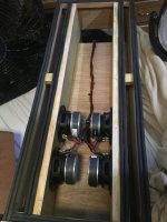
So no matter what I had to avoid that spot because that spot was a lot of trouble. in fact if I hasvir really really loud and it lit that off that hurt like heck no matter what. I had to avoid that spot because that spot was a lot of trouble in fact to Its loaded up with random vibration ringing chaos what have you… No cabinet shaking pretty good if it’s in contact with anything it’s really screaming and it does over and over again if that’s in the part of music you’re screwed.
Relating to the ideas presented in post #13 i had i chance to do som every rudimentary measurements outside.
Sub and mic placed with 1 meter distance on a plywood plate (approx 110*90cm). Plate placed on grass. Nearest brick structure was around 6meters away. A little wind that day and measuring at low volumes so noisy waveforms.
I believe that the mic i pretty linear to at least 40Hz, but I have no idea about absolute sound-level.
First: The tapped "horn" with right angles (the drawing to the right in post #13.


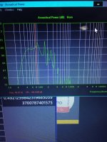
To compare model and measurement, I scaled the measurement, made it transparent and placed it over the HR-data: (not pretty, - I know ).
As I have no reference for the measurement the box could be 20dB less efficient than the simulation, but I hope that the scaling used below is realistic.
Blue is measurement, Yellow is HR-data-export

If the scaling used above is realistic the TH works better than expected and I could paint the box and call it a day. If it was a commercial product sensitivity/bandwith could be labelled as 50-200Hz 98dB. Thats pretty respectable from a cheap driver and some trash-plywood.
EDIT: OK, maybe I was bit optimistic in the scaling. Does this look more realistic:

Does it look realistic to you guys?
Kind regards Troels Mejer
Sub and mic placed with 1 meter distance on a plywood plate (approx 110*90cm). Plate placed on grass. Nearest brick structure was around 6meters away. A little wind that day and measuring at low volumes so noisy waveforms.
I believe that the mic i pretty linear to at least 40Hz, but I have no idea about absolute sound-level.
First: The tapped "horn" with right angles (the drawing to the right in post #13.
To compare model and measurement, I scaled the measurement, made it transparent and placed it over the HR-data: (not pretty, - I know ).
As I have no reference for the measurement the box could be 20dB less efficient than the simulation, but I hope that the scaling used below is realistic.
Blue is measurement, Yellow is HR-data-export
If the scaling used above is realistic the TH works better than expected and I could paint the box and call it a day. If it was a commercial product sensitivity/bandwith could be labelled as 50-200Hz 98dB. Thats pretty respectable from a cheap driver and some trash-plywood.
EDIT: OK, maybe I was bit optimistic in the scaling. Does this look more realistic:
Does it look realistic to you guys?
Kind regards Troels Mejer
Last edited:
The latter looks more realistic. Hornresp does not include the impact of box losses in its TH model (there is a way to "ratch" it however), so expect the actual peaks and dips to be a bit less in magnitude than what the Hornresp sim predicts.
Out to the 2nd dip, yes IME, I've yet to see any actual TH measurements without a low pass filter, though probably still 'close enough' considering even an empty TL's acoustic inertance is strong enough to damp resonances > 500 Hz.

How does the response compared to a Hornresp sim'd response of the driver in a box that size vented to the Fb of the TH?
Something like this. BR should probably be tuned lower. IF I were to made a standard BR I would make a smaller box.How does the response compared to a Hornresp sim'd response of the driver in a box that size vented to the Fb of the TH?
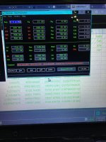
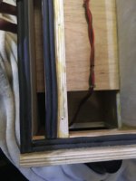
300 cm2 and 600 for a single driver I’m sorry I didn’t notice that.. And an L45 at 15-30 cm which is nice because this is now a bunch of smaller rectangles inside of one rectangle and then L4 five is exposed at the very end As threaded inserts and cap screws allow bolt on fine-tuning which is great.
- Home
- Loudspeakers
- Subwoofers
- Tapped Horn Vs 6th order par.bandpass ?