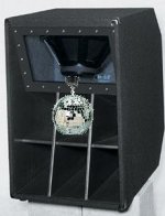
The design is a tapped horn, however it's going to look a lot like a scoop, in that i'll have a plexiglass window in front of the drivers for the kiddies to look at.
I don't follow..
No; most of the time i'll be running them in 1pi, but I've done all of my modeling in 2pi just in case I should need to take them outdoors.
I see most of the TH confusion has been addressed, however I need to make one more comment. In my mind, 1pi is 'facing' the wall, usually 6"-18" away depending on cabinet, and that will mean the kiddie's will miss out on all of that plexiglass/speaker/neon goodness... that I think was lurking in the back of your mind....
And yes, folding is a beast, and trial/error is necessary. Hornresp gets you close, but you must be willing to take it from there. Scott's (screamersusa) design was trial tested ALOT, and that was how he found 3db at 100hz by just eliminating a reflector.
Rather loose a few dB then the looks. Everybody knows that plexi-neon gains 3-4 dB overall anyway. It's simple physics really.
Best regards Johan
Best regards Johan
Rather loose a few dB then the looks. Everybody knows that plexi-neon gains 3-4 dB overall anyway. It's simple physics really.
Best regards Johan
Hey... I thought I remembered the rule for neon from my 12v days.... but you wouldn't know the physics for adding mirror ball would you? (I've lost my totally awesome dj guide...)
(all humor in bad taste... apologies for those offended... thanks for the laugh johan)
Attachments
Ok, so after a few distractions in my personal life, I was able to get back to this and re-model significantly using the suggestions provided, along with my new understanding of the theory based on the feedback from you guys.
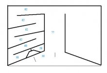
I found really nice looking response curves when using 4 drivers. I switched back to JBL 2226H's and the upper corner in usable response is now about 220hz. The "challenge" is now driver placement. If I do a line of four drivers in a row (let's call this a "conventional tapped horn"), it takes up a lot of space - 70 something inches wide. But I whipped up another type of design which still seems to follow all of the theory. Please see the attached diagram.
You're looking at a top view, the solid black lines indicate wood. The other misc. lines are used to illustrate things which should be obvious in the drawing. The lengths given are L12 and each segment of L23, in centemeters. I only illustrated one half of the box - that half will also have two drivers stacked vertically, and the other half will be the same inverse.
My questions are these: 1) Does this still comprise a tapped horn? 2) Do I need a wall along the 77cm segment to separate the two halves, or can they combine just fine? 3) Did I miss anything?
Assuming this is all kosher, I will post displacement curves, response curves, and the hornresp input file for this design using the 2226H's. The Eminence Lab15's that I was modeling with had this nasty dip at 60 to 80hz, which is the lowest point in the response between the lower and upper corners, and is a full 5db down from the design w/ the JBL 2226H's. For that reason, and because I don't believe in EQing that up since it negatively affects the headroom of the amp, I decided to go back to the JBLs.
Feedback is appreciated!
Attachments
A comment or two:
This is not to be mean or to put you down just short and to the point.
The drawing you have posted is not going to work.
The right section is not even remotely coupled to the left section. Think fluid flow and where the path of least resistance is and you will be able to visualize what will happen to the right section.
In the real world this box will have a very peaked response not flat at all. My guess is that Hornresp is telling you that extra section is needed to get a smooth top end. THe info from Hornresp is right . The layout needs some TLC.
What looks promising is your good idea of squeezing the horn contour into the available space on the left. That is the beginning of the horn folding fun!
You may want to post the design page and check what you have done against it. For instance the driver location is modeled as a red and green circle. This is the front and back of the driver or combined drivers. This little bit of info tripped me up quite a few times!
But otherwise you show ingenuity in layout. What you will come up with after considering how sections of a resonant system need to be laid out I'm sure you will get where you are trying to go.
Mark
Mark,
I think if you look at his middle paragraph you'll see he only illustrated half the box and the right will be a mirror image of the left.
I think if you look at his middle paragraph you'll see he only illustrated half the box and the right will be a mirror image of the left.
Well it's not the first time I have been accused of being blind!
Hi Cal.
Thank's for pointing that out for me.
But the statement about the air taking the path of least resistance is the one that is going to hold the design to the harsh reality of the real world.
As drawn even with the mirror of the left side on the right side it is still not a truly resonant system. A tapped horn basically uses the length and location of driver within the path length to create two points of greater output. These are the resonant points. We all try to get rid of that big sag in between the low point defined by the chamber length, and the high point defined by the location of the driver relative to the mouth. How the two peaks end up reacting with each other is also smoothed out by the size and location of the mouth.
I have folded and messed up enough of these things to admit to a very steep learning curve. I messed up at least 5 of them. But once you get your head around what the tapped horn is attempting to do it starts to make sense.
Lately I'm working on front loaded horns. They are bigger but easier to tickle the SPL's out of. A truly optimized tapped horn is a work of art and a labor of love! The number of drivers that are available that really work in a tapped horn you can count on two hands.
Mark
I'm having a hard time wrapping my head around that one. You have a left and right driver chamber that combine in the center. Both chambers are moving air with the same drivers and the same program material (drivers are arranged 4P), thus they're completely in phase (assuming identical internals on both sides of the box). It seems to me that the path of least resistance is in fact the 77cm path out the mouth of the horn.
Can you point me to an in-depth reference on tapped horn theory so I can figure out what's missing from this conversation? And, based on your assertion, would a wall along the 77cm path to separate the driver chambers not solve for this?
Can you point me to an in-depth reference on tapped horn theory so I can figure out what's missing from this conversation? And, based on your assertion, would a wall along the 77cm path to separate the driver chambers not solve for this?
I'm having a hard time wrapping my head around that one. You have a left and right driver chamber that combine in the center. Both chambers are moving air with the same drivers and the same program material (drivers are arranged 4P), thus they're completely in phase (assuming identical internals on both sides of the box). It seems to me that the path of least resistance is in fact the 77cm path out the mouth of the horn.
First let me apologize for not reading carefully and looking even more carefully.
Insert red face here!
Think first. Type second!
OK I'm getting your assertion about the flow paths and I completely missed the second driver. My own fault.
Now back to what I can comment about that is actually constructive.
Given I finally understand what you have in your drawing. You have two horn paths that are meeting in the middle section. Have you modeled this as two seperate tapped horns in Hornresp and done a combined response? If you have and you are getting the desired SPL figures it should work.
If you want a better critique post your input screen. I see what I can do. But I would have to know what you are after in terms of SPL and frequency response. There are a couple of gents on this forum who are very good at modeling this type of box. If I can get my foot out of my mouth long enough I may be able to help out.
Can you point me to an in-depth reference on tapped horn theory so I can figure out what's missing from this conversation? And, based on your assertion, would a wall along the 77cm path to separate the driver chambers not solve for this?
How about no!
There is no real explanation of how tapped horns work that is available and actually gives you all the design info. I gave you the bare bones of how they work. But the box is a very careful balance between driver and cabinet. Most of us try using a favorite driver and hoping that it will work. The truth to be told is that if you have a optimally designed cabinet when modeling in 2 Pi space it should have 7 db gain over the raw driver or even better. That requires a very intelligent driver choice and then designing the cabinet around the driver. Take note of what Danley is using. Take note of what Mr. Cowan has modeled and built. Those are the characteristics that give the best response in a tapped horn type cabinet. Danley squeezes out 8 to 9 db. He is a wizard to be sure.
Mark
First let me apologize for not reading carefully and looking even more carefully.
No prob.. the details will get you 🙂
(and me - which is why I'm trying to get feedback at every stage from knowledgeable people, and not from a microphone after wasting a bunch of wood...).
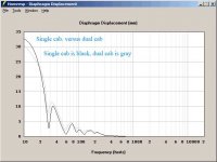
Given I finally understand what you have in your drawing. You have two horn paths that are meeting in the middle section. Have you modeled this as two seperate tapped horns in Hornresp and done a combined response? If you have and you are getting the desired SPL figures it should work.
I just did - Hornresp did basically what we expected it to; see the attached diagrams. I'm not surprised that the displacement increased - that's reasonable because the horn chambers aren't physically coupled and probably don't benefit as much from the large size of one versus the smaller size of two. That, I believe, is why JBL stuck that thing that looks like a phasing plug, in the middle of their 4550a's - it makes the horn "look bigger" to each driver individually. But I am kind of surprised that this one plays lower when modeled as two cabinets (the lower corner extends down a few more Hz) - that's the first time I've ever seen anything like that. I always think of those combined response charts as a purely electrical thing - that is, since Hornresp won't know anything about the way you stack multiple boxes, it can't possibly account for any of the physical aspects of multiple boxes - only the electrical ones. But the result would seem to imply that there is some kind of physical effect in play too - the only one it can consider, I think, is the mouth size of each individual box and then make them additive in some way. And I did leave the mouth size the same between the two comparisons - that could easily account for the difference.
If you want a better critique post your input screen. I see what I can do. But I would have to know what you are after in terms of SPL and frequency response. There are a couple of gents on this forum who are very good at modeling this type of box. If I can get my foot out of my mouth long enough I may be able to help out.
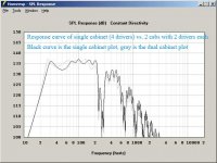
Sure thing. Time-permitting, I will model for a couple more hours on what I have and then send my input screen and import file to the forum. But just to give you an idea of what I'm getting - 4 x 2226H's with 41 volts in yields the SPL curve I've posted in black.
I just wanted some initial feedback on whether the design would work (I can't imagine why it wouldn't). As a bonus, I can just picture this thing having an incredibly long throw by virtue of all the sound collision going on out in front of the mouth. I view this thing like a small line array. Two or three stacked would be devastating... hopefully 🙂
Thanks for the feedback thus far.
If you are modeling the box you have to keep this in mind that the two sections will sum. But each section sees more or less have of the mouth. So when you try modeling them as a two high stack you have to take into account the 50% reduction in the mouth size.
Short story your two box post is a bit off from the get go. The whole thing has to be modeled as two separate boxes left and right with half the mouth area. Then do a sum for two boxes.
Mark
Short story your two box post is a bit off from the get go. The whole thing has to be modeled as two separate boxes left and right with half the mouth area. Then do a sum for two boxes.
Mark
Solution 🙂
If the driver is facing the wall...
Stick a big mirror on the wall!
Or illuminate the chamber, put in a (web)cam and display what's going on in there on your plasma display or projector...
If the driver is facing the wall...
Stick a big mirror on the wall!
Or illuminate the chamber, put in a (web)cam and display what's going on in there on your plasma display or projector...

This is interesting!
I'm designing a tham12-style cab with WAE hornresp input and we take the magnet/driver size into account by making the mouth wider, does no one else do this?
By the way, the 1dB difference from front / rear loading is very interesting, which is most efficient?
We ended up with a different folding than the WAE, to me it took up more space.
I'm designing a tham12-style cab with WAE hornresp input and we take the magnet/driver size into account by making the mouth wider, does no one else do this?
I don't think people are factoring in the volume of the driver when they model tapped horns. I'm thinking of doing a TH for my truck. I had the original size of the mouth at 1,651.61cm^2 (16" x 16"). If I build it, I am going to use a 1,961.29cm^2 (19" x 16") mouth to account for the 0.5ft^3 volume of the driver and expect the 16in^2 frequency response.
By the way, the 1dB difference from front / rear loading is very interesting, which is most efficient?
We ended up with a different folding than the WAE, to me it took up more space.
Some do, some don't; there's advantages to either depending on the driver, desired alignment.
GM
GM
That makes no sense to me!
Either you take the volume into account or not, the reality will be the same no matter what.
Question is if I should simulate it? -We did & we did compensate for this.
Some must have been working with this before
If u don't I guess there will be a narrow spot where the driver is?
Either you take the volume into account or not, the reality will be the same no matter what.
Question is if I should simulate it? -We did & we did compensate for this.
Some must have been working with this before
If u don't I guess there will be a narrow spot where the driver is?
Last edited:
This is interesting!
I'm designing a tham12-style cab with WAE hornresp input and we take the magnet/driver size into account by making the mouth wider, does no one else do this?
By the way, the 1dB difference from front / rear loading is very interesting, which is most efficient?
We ended up with a different folding than the WAE, to me it took up more space.
From what I've read in the past, speaker basket in the throat affects the response more than speaker basket in the mouth.
- Status
- Not open for further replies.
- Home
- Loudspeakers
- Subwoofers
- Tapped horn theory