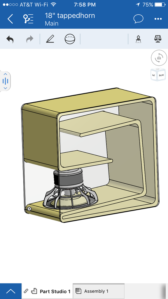
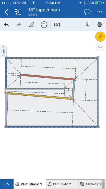
I have made a 3d model of a tapped horn / tapped pipe where the different variables for throat / mouth and length can be changed and it will redraw itself to the new parameters automatically. This is a part of a set of subs that I plan to build, but I think that the idea of it, the 3d model that you can plug numbers into is a good idea for the community to have, and would like to have some people try it out to see if it's something worth doing more of.
Link to model
DISCLAIMERS: (please read)
The model is made in Onshape. You need to signup for a free account to edit the model, but there is not software to install it's all in browser, unless you plan to use a mobile device. Then there are apps for that (mobile is a better UX actually, I used my phone to make the model.)
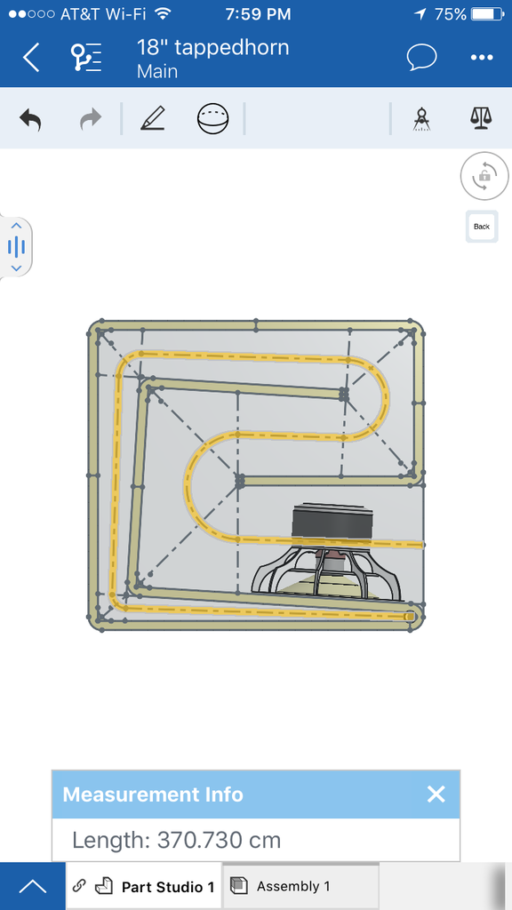
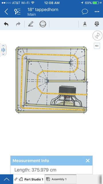
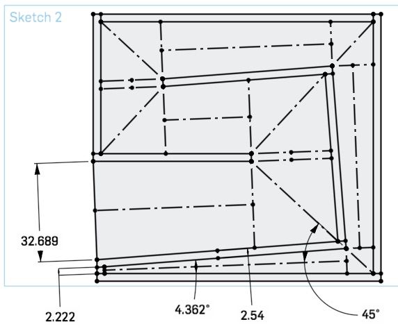
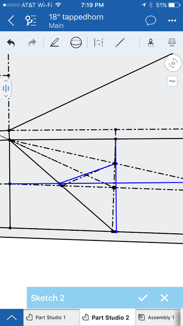
The length variable is NOT accurate, however if you view "Sketch2" there is a dashed line running down the center of the horn, select all of it's segments then tap the calipers icon on the top and it will give you a very close approximation of the actual length, then you can adjust the variable up or down and remeasure. I'm not sure how to fix that. I tried using a correction algorithm that got it closer, but it still wasn't right.
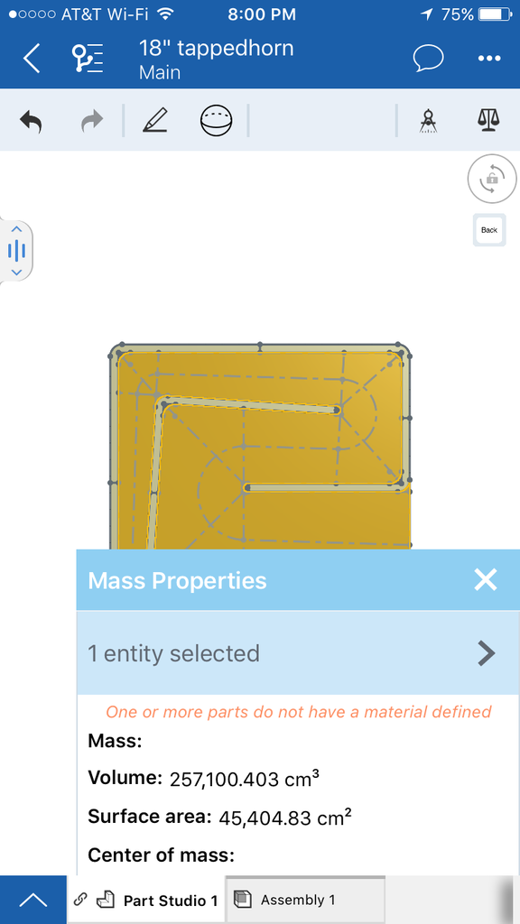
If you select part4 and press the scales icon it will tell you the total volume of the horn.
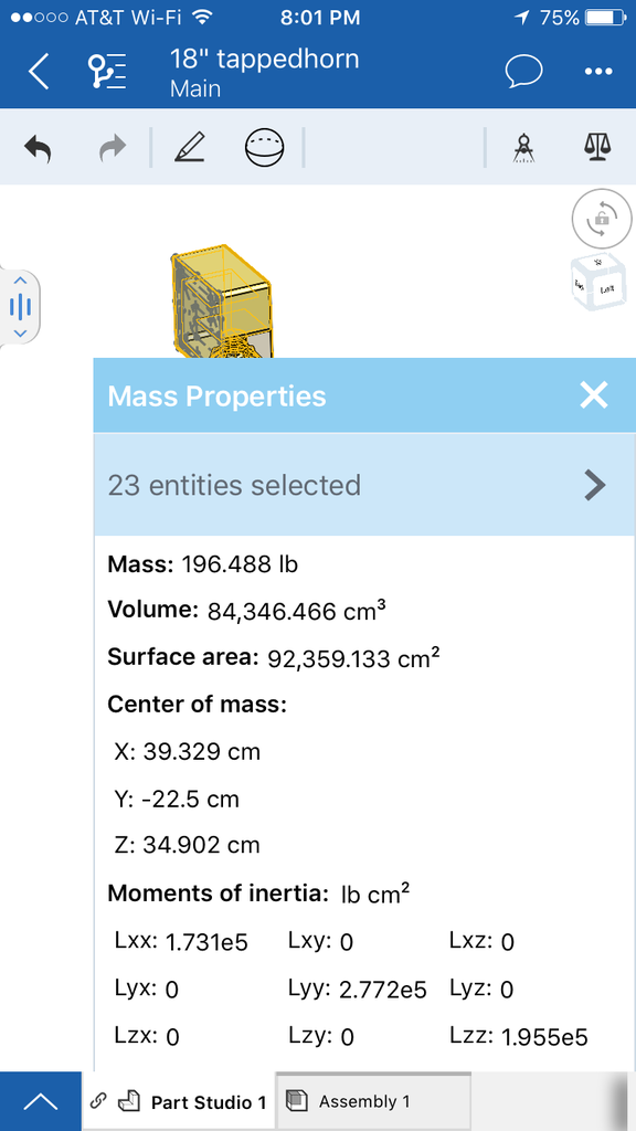
If you select all of the parts (except part4) it will give you an estimated weight (for plywood and polycarbonate and an as of now imaginary driver)
The model is meant for stacked cnc cut plywood with polycarbonate sides, if enough people think it's a useful idea then I will make a few for more affordable, less wasteful construction, and more flexible fold styles.
it's constant flare only, I haven't tried compound flares yet, not sure how that would behave.
If you go too high or low with the variables the model will twist itself into a knot, just hit undo and it will go back together. This isn't the most flexible folding style, but it looks really nice with clear sides and it keeps the mouth on the floor.
The driver in the model is one I'm designing custom for this sub, it's not done, and is just there to give a size reference.
Link to model
DISCLAIMERS: (please read)
The model is made in Onshape. You need to signup for a free account to edit the model, but there is not software to install it's all in browser, unless you plan to use a mobile device. Then there are apps for that (mobile is a better UX actually, I used my phone to make the model.)
The length variable is NOT accurate, however if you view "Sketch2" there is a dashed line running down the center of the horn, select all of it's segments then tap the calipers icon on the top and it will give you a very close approximation of the actual length, then you can adjust the variable up or down and remeasure. I'm not sure how to fix that. I tried using a correction algorithm that got it closer, but it still wasn't right.
If you select part4 and press the scales icon it will tell you the total volume of the horn.
If you select all of the parts (except part4) it will give you an estimated weight (for plywood and polycarbonate and an as of now imaginary driver)
The model is meant for stacked cnc cut plywood with polycarbonate sides, if enough people think it's a useful idea then I will make a few for more affordable, less wasteful construction, and more flexible fold styles.
it's constant flare only, I haven't tried compound flares yet, not sure how that would behave.
If you go too high or low with the variables the model will twist itself into a knot, just hit undo and it will go back together. This isn't the most flexible folding style, but it looks really nice with clear sides and it keeps the mouth on the floor.
The driver in the model is one I'm designing custom for this sub, it's not done, and is just there to give a size reference.
Last edited:
This looks very similar to Brian Steele's Horn Folding Spreadsheet, it even offers the same layout. I haven't ever used his, so not sure what it's capable of (if it can do complex flares or just a constant flare) but the thread is here, actually I'll just link to a post in the thread that shows a screenshot of his spreadsheet so you can see what it does.
http://www.diyaudio.com/forums/subwoofers/171747-spreadsheet-folded-horn-layouts-22.html#post4443437
Anyway, I like stuff like this, as long as it's accurate. I see you are using advanced centerline, so that's good. If it's accurate you get a thumbs up.
I tried to convince the Leonard Audio tl.app guy to increase the capabilities of his program to include simulation from a schematic drawing (which wouldn't have been that hard considering what the program already does) but he didn't bite. A program that can simulate using a drawing as inputs would be really cool. But I guess that's OT.
This looks very similar to Brian Steele's Horn Folding Spreadsheet, it even offers the same layout. I haven't ever used his, so not sure what it's capable of (if it can do complex flares or just a constant flare) but the thread is here, actually I'll just link to a post in the thread that shows a screenshot of his spreadsheet so you can see what it does.
http://www.diyaudio.com/forums/subwoofers/171747-spreadsheet-folded-horn-layouts-22.html#post4443437
There are a number of spreadsheets at in that thread, one for each type of fold that's commonly used here. Best to start from the end of the thread and work your way up, as the spreadsheets went through several versions.
Anyway, I like stuff like this, as long as it's accurate. I see you are using advanced centerline, so that's good. If it's accurate you get a thumbs up.
It's not quite advanced-centerline. He's using curves through the corners, which can make the estimated length a bit longer than that estimated via the advanced-centerline method. I also suggest taking cross-sectionals that are perpendicular to the centerline, though that could lead to some "estimations" having to be made at the beginning and the end of the line if the termination of the horn at the mouth and throat are not perpendicular to the centerline. The later versions of my spreadsheets take this into consideration.
Anyway, it looks like a pretty decent utility. Certainly looks easier to use than my spreadsheets... 🙂
It will be easy to change it to advanced centerline if that is a more accurate measurement. The dashed line does not control any part of the model, and is just used for the measurement so it can be changed without effecting anything else.
There are a number of spreadsheets at in that thread, one for each type of fold that's commonly used here. Best to start from the end of the thread and work your way up, as the spreadsheets went through several versions.
Sorry, I did read through it but that was a long time ago and haven't tried it because I haven't had to fold anything lately.
It's not quite advanced-centerline.
It looked like it was on my small screen, guess I should have looked closer.
Sketch3 now contains what I believe is the advanced centerline method. I'm not certain that I've done it correctly as it measures longer than the previous tangent curve method.
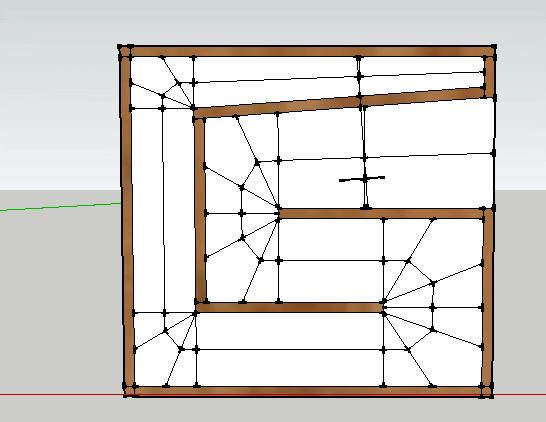
I have updated the model to use flat panel construction because it will be useful for more people. After experimenting (a lot) with Advanced centerline and other techniques I've come up with something different altogether. The new technique breaks up the horn into straight and corner sections similar to the advanced centerline technique and results in an exact volume match, both section for section, and as a combined volume.
I think that any variation from simulation that appears as a shift in tuning of path length should be accounted for in simulation. Measurement of path length is not the place to correct for this shift in tuning. It should be accounted for then the path length modified to match the offset from actual length to apparent sonic length. The difference being that using a measurement that is less accurate to the physical dimensions, and more accurate to the apparent sonic dimension masks the issue, but will never be totally accurate, and may not be consistent.
Edit: I forgot to say, the length variable is now accurate as well.
Last edited:
I think that any variation from simulation that appears as a shift in tuning of path length should be accounted for in simulation. Measurement of path length is not the place to correct for this shift in tuning. It should be accounted for then the path length modified to match the offset from actual length to apparent sonic length. The difference being that using a measurement that is less accurate to the physical dimensions, and more accurate to the apparent sonic dimension masks the issue, but will never be totally accurate, and may not be consistent.
Not sure exactly what you are trying to say here, but it sounds like you don't think advanced centerline is totally accurate or consistent.
As far as i'm concerned advanced centerline is tried and proven and the most accurate and consistent you can get without going way overboard (see second quoted post below).
Please review these two posts by Soho54, who developed the advanced centerline method and did more work on this than any of us can imagine. But long story short - if you are not using advanced centerline I would never use your app or recommend it.
I came up with it through a lot of research, and trial and error. About two years ago I got feed up with the "common knowledge" surrounding horns, so I threw it all out and started over from scratch. I read everything I could by Keele, Edgar, Leach, and Danley looking for common threads. I have pages and pages of excel work exploring their different papers, and ideas from posts. I then went back to Rayleigh, found measured data on acoustic pressure around bends, and sourced fluid dynamic, FEA, and BEM simulations.
I then spent a lot of time trying different ideas out, coming from the view point of getting the simulation to match reality. I would work until I found something that worked for a certain folded horn, and then tried it on another. You can find different ways to sim a single horn, but most of them fail when you try it on another. I kept redoing things until I found a way that works on all the horns I have tried it on.
In truth, every method you have there along with the 45deg, and SQRT of the product of the inside and outside path lengths works well enough on smaller bends in horn with only one to three corners. It is when you start to add more corners, or larger flares that they start falling away. The .707 one is more of a mid horn up thing.
Up until ~6months ago I actually used different methods for different corner setups, but in the end after dozens of more tests I have found that using the single method produces the most consistent results no matter the corner number, or geometry.
The problem with most of them is that they are inflexible, don't scale well, and do not account for the extra volume in a non-squared corner that will add path length. The bass horn system I came up with does.
The Danley quote is actually a key piece to the puzzle. If the volume around the corner is exactly the same as the straight line distance, then the acoustic path will be shorter than the straight line distance. That means a corner should have slightly more volume than it's straight sectioned counterpart, and adding even more volume will increase it's acoustic length beyond the straight sections length. It also means that if you know the volume is the same, and you path length sims longer than the real deal, you haven't measured the path through the corner correctly.
The nice thing about this method I found is that you can take a measured horn, create a sim from the plans that is equivalent. Then use the simulation output to refold the horn, and the results will be within a tolerance of mm to the original horn. It works in reverse as well. The only trick is learning where/when reflectors are needed, but it isn't hard to figure that part out. It is just a continuation of the line of thought stemming from the quote, and applying the same solutions.
I don't think it is the only way to do it, or even the best way. It just seems to work for me, and a few others.
From here - http://www.diyaudio.com/forums/subwoofers/175658-tham15-compact-15-tapped-horn-21.html#post2452977
What TD seems to be talking about is a different (more advanced) way to model a horn. What you do is model the straight sections as waveguides/ducts only, and the bends are modeled as base forces of mass/resistance/compliance, and not waveguide/duct elements.
AkAbak can do it, but getting it right is not easy. My experimental equations for the AcouMass and AcouResistance for one bend are longer than most of the full simple scripts I have posted in this thread.An externally hosted image should be here but it was not working when we last tested it.
If you look up those two elements (might as well check out AcouCompliance as well) in the AkAbak manual it will give you the idea, and base equations. Then you have to figure out how to apply it to bends with changing area, different degree corners, and frequencies. Just so you know the simple 90deg corner mass equation will not work right here, so don't waste your time there.
It is much simpler to just physically account for the path length, and model that way.
Something along the lines of this will give you good results with a horn with multiple bends.
You use each triangle section though the bend as a waveguide element. This will adjust the mass/resistance properties though the bends on it's own, and get it pretty darn close. If you do it correctly the FR and impedance peaks and dips will line up the the true measured ones. The Q of the peaks and dips will be a little different, and will generally be a little less in magnitude as the frequency rises, but you can get a very accurate model without you having to become a PhD level math whiz.
EDIT:I should add that this only works at sub frequencies. If you need bandwidth much above 150Hz you will want to learn the hard way. The dimensions through the bends must be less than 1/4WL of the frequencies in question.
From here - AkAbak for Dummies 😉 - Page 2 - AVS Forum | Home Theater Discussions And Reviews
What i am trying to say is that if there is a difference between the tuning of a folded horn and it's actual physical length, you do acount for the difference, and add that to your path legth ,but you don't make a different tape measure.
I think that the correct path would be acoustically modeling each corner, however a more appropriate shortcut would perhaps be a simple correction algorithm.
I will have to build several, or perhaps an adjustable rig, and record the difference each bend makes. The end result will be more accurate and more predictable end results.
For a straight horn the actual length and the acoustic length are the same (add in an end correction for the acoustic length, but the simulator does that for you).
Once you start folding and going around bends the acoustic length is no longer the same as the centerline length. Who said centerline is the actual length anyway? The length of a folded 3d object is complex, acoustically it's not the straight line down the center because that's not how air flows.
Danley's famous quote from his Labhorn notes goes as follows:
This is the quote Soho54 was referring to when he developed the advanced centerline method and he thoroughly vetted the method himself, and it has been further proven by many people and many builds since then.
So unless you want to use Akabak as your only simulator and use AcouMass, AcouResistance and AcouCompliance scripts in which the bend definitions are the longest and hardest part of the script, you have to pick one of these methods for determining length.
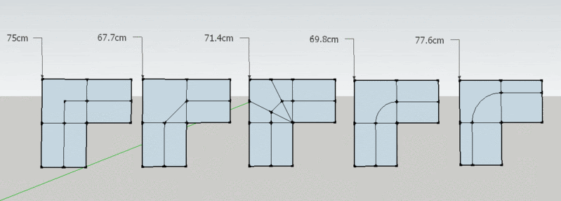
Far left is centerline. Far right is the curves you were originally using in post 1. Neither of these are accurate, this is proven. Neither of middle left or middle right are accurate either.
Only the middle method (advanced centerline) is accurate. There is no other simple method that is accurate.
You can attempt to reinvent the wheel if you want but advanced centerline is proven and accurate. The rest of us will be using advanced centerline while you do your experiments and eventually end up at the same conclusion.
Just to be really really clear here - centerline method is not accurate. Choosing the more accurate path through the bend is not making a different tape measure, it's using a tape measure to measure the best path.
Once you start folding and going around bends the acoustic length is no longer the same as the centerline length. Who said centerline is the actual length anyway? The length of a folded 3d object is complex, acoustically it's not the straight line down the center because that's not how air flows.
Danley's famous quote from his Labhorn notes goes as follows:
"A word about folding, one mistake made in horn folding is to make the horn passage significantly less volume that it was when straight. The air in a bend has a rotary motion and so momentarily has rotational properties, the effect of this is that the air has slightly more mass than in a straight section. This in turn allows a small reduction in acoustic length for that section but it is small. When I lay out a bend usually try to keep the total volume close to that of a straight horn."
This is the quote Soho54 was referring to when he developed the advanced centerline method and he thoroughly vetted the method himself, and it has been further proven by many people and many builds since then.
So unless you want to use Akabak as your only simulator and use AcouMass, AcouResistance and AcouCompliance scripts in which the bend definitions are the longest and hardest part of the script, you have to pick one of these methods for determining length.
Far left is centerline. Far right is the curves you were originally using in post 1. Neither of these are accurate, this is proven. Neither of middle left or middle right are accurate either.
Only the middle method (advanced centerline) is accurate. There is no other simple method that is accurate.
You can attempt to reinvent the wheel if you want but advanced centerline is proven and accurate. The rest of us will be using advanced centerline while you do your experiments and eventually end up at the same conclusion.
Just to be really really clear here - centerline method is not accurate. Choosing the more accurate path through the bend is not making a different tape measure, it's using a tape measure to measure the best path.
Last edited:
I wrote out a ton of words to explain my point of view better, as I feel there was a misunderstanding of what I meant, but after reading it to myself this is the only part that really matters in the end:
Advanced centerline is easy enough to add to my model and I don't see any reason not to, choice is good, also anyone can fork my model and make changes as they please to measure however they feel they want to. I think that the more people participating the better. The idea is to make it easy for diyers to take an idea from hornresp to 3d design without mucking about in cad for hours, just plug in your numbers and print out a cut sheet.
Advanced centerline is easy enough to add to my model and I don't see any reason not to, choice is good, also anyone can fork my model and make changes as they please to measure however they feel they want to. I think that the more people participating the better. The idea is to make it easy for diyers to take an idea from hornresp to 3d design without mucking about in cad for hours, just plug in your numbers and print out a cut sheet.
Hi Sexiewasd,
Looks very impressive, and would be a wonderful tool. How hard is it to get to other layouts, e.g.: single and double fold tapped horns, and will it be possible to enter reverse tapped horn values (S1 > S2 ... > S5)?
Some single folds:
Cowan Audio 30Hz tapped horn:
William Cowan's Homepage
Volvotreter's Eminence tapped horn:
The Eminence 20Hz Tapped Horn – Volvotreter Homepage
Don Snyder's LAB12 double fold TH:
http://www.diyaudio.com/forums/subwoofers/143714-lab12-tapped-horn.html
Regards,
Just quickly reversed the values and it seams to handle it well enough.
The wedge shape in the throat make a lot less sense when it's that large, so it might be worth changing to a flat board even though it would be less accurate.
I think that i will handle different folding patterns as separate models in the same project, (tabs on the bottom). Unless Onshape adds global variables the numbers will have to be entered for each one.
I do have one question about advanced centerline. I want to make sure that it is implemented correctly.
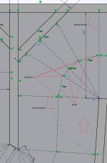
The blue line is parallel to the first and second straight sections centerlines. The dotted line is connected to the midpoints. Which is correct? I have been assuming midpoints, but I haven't been able to find that written anywhere.
The blue line is parallel to the first and second straight sections centerlines. The dotted line is connected to the midpoints. Which is correct? I have been assuming midpoints, but I haven't been able to find that written anywhere.
Last edited:
This is the way I did it.
The lines are always connected to the midpoints of the width lines.
The 3 path lines around an approx 90 deg bend are equal
The first width line at the beginning of the bend is perpendicular to the preceding path line.
The final width line is perpendicular to the outside face.
Attached screen grab shows a Solidworks path sketch as used to generate the unfolded path length. I turned on the sketch relation symbols (The green marks)
Extra labelling added with red annotation lines.
Hope that helps!
Xoc1
Attachments
Hi Xoc1,
Nice example. You are showing the advanced corner method applied to a corner w/ deflector, how do you apply it to a corner w/o deflector? Do you still shoot for equal segment lengths?
Regards,
Nice example. You are showing the advanced corner method applied to a corner w/ deflector, how do you apply it to a corner w/o deflector? Do you still shoot for equal segment lengths?
Regards,
Yes I use exactly the same method.
This would unsurprisingly result in a slightly longer path length - But of course there would be more volume around the bend.
Regards Xoc1
This would unsurprisingly result in a slightly longer path length - But of course there would be more volume around the bend.
Regards Xoc1
Yes I use exactly the same method.
This would unsurprisingly result in a slightly longer path length - But of course there would be more volume around the bend.
Regards Xoc1
I use a simple rule when laying out the path - for any sample point where the centerline passes through a cross-section line without bending, the centerline should be orthogonal to the cross-section line. This usually results in the cross-section lines never being at right angles to any sides of the horn's path, unless that section of the horn is not expanding or contracting. When laying out the sample points for the path, none of them should violate this rule.
For the purposes of the discussion orthogonal = perpendicular.
I agree that the perpendicular rule is the way to construct the width lines. Where I differed is at the exit of the bend. Here I have chosen to construct the width line perpendicular to the outside wall. The reasoning behind this is that it represents the shortest distance. You could easily change the geometry to make the width line perpendicular to the following path line. In practice the difference is probably tiny. In the example I posted changing the width line geometry at the exit of the bend makes it 0.12mm longer. Far less then my construction tolerance in the real world!
I agree that the perpendicular rule is the way to construct the width lines. Where I differed is at the exit of the bend. Here I have chosen to construct the width line perpendicular to the outside wall. The reasoning behind this is that it represents the shortest distance. You could easily change the geometry to make the width line perpendicular to the following path line. In practice the difference is probably tiny. In the example I posted changing the width line geometry at the exit of the bend makes it 0.12mm longer. Far less then my construction tolerance in the real world!
Can't find the model
Hi,
I cannot find the model on Onshape anymore. Is it there still?
Best,
Selim
Hi,
I cannot find the model on Onshape anymore. Is it there still?
Best,
Selim
- Home
- Loudspeakers
- Subwoofers
- Tapped horn, 3d model / automatic folding