hello,
i was thinking about this enclosure for 6" fullranger:
"straight Nautilus"
straight tapered tube about 60" long.
driver mounted on wide end, 1" opening on other.
but prior to me making it:
has anyone tried this and how does this box model?
like a transmission line?
thanks,
herman
i was thinking about this enclosure for 6" fullranger:
"straight Nautilus"
straight tapered tube about 60" long.
driver mounted on wide end, 1" opening on other.
but prior to me making it:
has anyone tried this and how does this box model?
like a transmission line?
thanks,
herman
There was a thread some time back about a foam-core build called "Nautaloss".
Yes, it will model as a transmission line. If the terminus is closed, it will be a ½-wavelength resonator. These are usually stuffed the whole length in order to absorb the back wave. It should perform roughly like a sealed enclosure, possibly cleaner midrange, never heard one though. If you have the terminus open, it will be a ¼-wavelength resonator, probably not what you want here and is a whole different design approach. If you have to leave the terminus open, use progressively denser stuffing down the line and stuff the opening as well. Probably best to use a driver with low-ish Fs (<60Hz )and medium Qts (0.45-0.7).
Yes, it will model as a transmission line. If the terminus is closed, it will be a ½-wavelength resonator. These are usually stuffed the whole length in order to absorb the back wave. It should perform roughly like a sealed enclosure, possibly cleaner midrange, never heard one though. If you have the terminus open, it will be a ¼-wavelength resonator, probably not what you want here and is a whole different design approach. If you have to leave the terminus open, use progressively denser stuffing down the line and stuff the opening as well. Probably best to use a driver with low-ish Fs (<60Hz )and medium Qts (0.45-0.7).
Yes, there is the uncoiled Nautaloss or 'dagger' sealed TL. It is very easy to make with 5 pieces of wood and stuffed progressively. It behaves like an infinite baffle. You are far better off to coil it up into a spiral to save space and it is not hard to make with foam core. It is one of the best sounding speakers I have built - very neutral flat response. Use the Vifa TC9FD driver - doesn't get much smoother response wise or lower in distortion even though priced very low.
http://www.diyaudio.com/forums/full-range/247598-nautaloss-ref-monitor-38.html#post3851303
Here is what it is capable of:
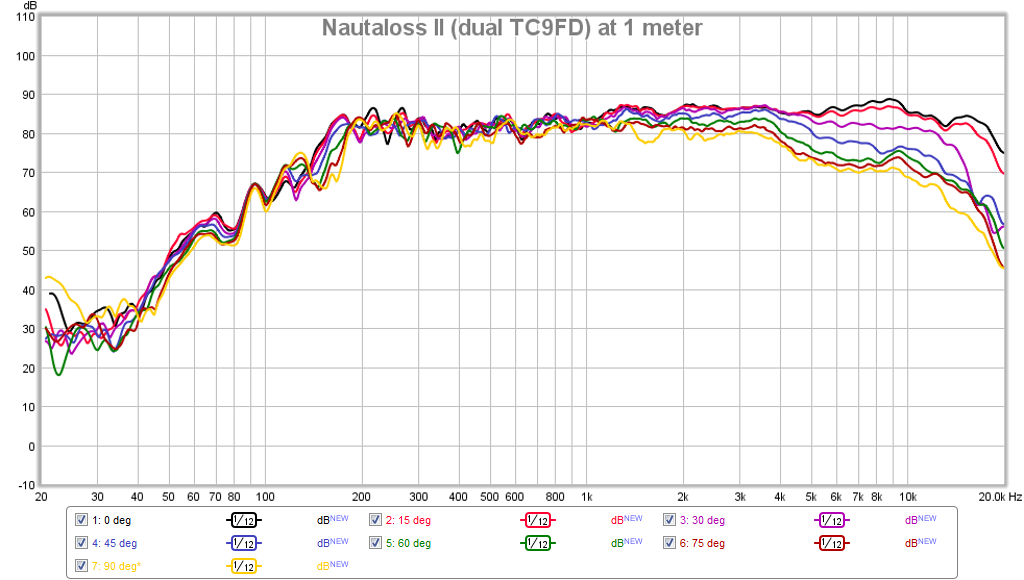
Needs a sub woofer though as sealed alignments don't go much below 150 Hz. In the same thread there is also a Nautaloss subwoofer.
http://www.diyaudio.com/forums/full-range/247598-nautaloss-ref-monitor-38.html#post3851303
Here is what it is capable of:
Needs a sub woofer though as sealed alignments don't go much below 150 Hz. In the same thread there is also a Nautaloss subwoofer.
Or start with a > 1.0 Qt driver.........
GM
I do have a pair of pro 6.5" midbass with higher than expected Kms/Fs/Qts, the latter two coming in ~25Hz and 0.35 too high respectively at ~86Hz and ~0.9. :/ Such an enclosure might be saner than a whole bunch of vented atrocities I've gone nuts trying to simulate with decent results anyway.
 I'd likely lose the fairly solid ~60Hz extension I was going for with the factory data.
Them big'ol Isophon 8"x12" coax I got might be neat in there with Fs~60Hz and Qt~0.9.
Brand, model? Prosound drivers usually adhere to a much lower Fs shift than consumer products, so that once exercised at high power will be 'close enough' to advertised. Maybe yours just need to be stuck in small sealed cabs and 'lit up' with an electric guitar. 😉
GM
GM
Brand, model? Prosound drivers usually adhere to a much lower Fs shift than consumer products, so that once exercised at high power will be 'close enough' to advertised. Maybe yours just need to be stuck in small sealed cabs and 'lit up' with an electric guitar. 😉
GM
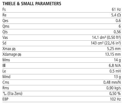
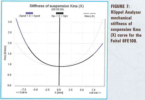
Faital 6FE100. I had a thread over in multi-way where I initially had a few measurement issues. After sorting these out, it basically seems Cms is about half what it should be and the rest of the data naturally follows suit.
Factory data:
2008 Voice Coil / Vance Dickason data:
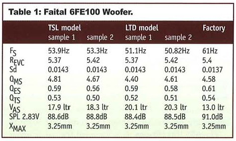
Data I measured: (~2V drive level)
Fs = 86.19 Hz
Re = 5.60 ohms[dc]
Le = 251.23 uH
Qt = 0.92
Qes = 1.00
Qms = 11.00
Mms = 14.39 grams
Rms = 0.707299 kg/s
Cms = 0.000239 m/N
Vas = 6.86 liters
Sd= 142.93 cm^2
Bl = 6.585896 Tm
ETA = 0.42 %
Lp(2.83V/1m) = 89.84 dB
Added Mass Method:
Added mass = 37.00 grams
Diameter= 13.49 cm
I pushed some ~20Hz-30Hz sine at ~12V into them for a few hours with zero measured change after the motor had cooled.
The upside to that low Cms is high excursion-limited power handling. 🙂 I don't see how Fs could be lower if I measured at higher excursion since the suspension only gets stiffer and things would start to be non-linear anyway. Not sure I'll ever drive them hard enough in everyday use to loosen it up too. Maybe I'll give'em some more time on the "burner" and hope for the best.
I got some half-decent simulated results with rather large stuffed TL's, bu the aim was <30L and fair 50Hz-60Hz extension with this project. I'm thinking ~20L sealed or lossy spiral with their backs to a wall, give up the bass and be done with it. Should be decent enough for shop speakers.
noviygera,
Did you have a specific driver in mind?
GM,
The lossy spiral looks fair enough as far as I can simulate this in HR, but I just remembered my best result so far from a few days ago. It's a 48" long ~40L ML-Voigt (expanding pipe) with driver tap ~42% (20") and a ton of stuffing in the whole length. Damps the Z nicely to ~ a single (upper) low-magnitude peak, gives a much reduced ~100Hz hump and gets fair extension. I have no practical experience with such a combo though, can only sim and guess how it'd turn out.
6.5 inch l.cao
L.cao f6:

Not planning on spiral. Just a tapered tube or long pyramid (four sides plywood).
60 inches long transmission line, so the tapered end is open. Is it too short?
L.cao f6:
Not planning on spiral. Just a tapered tube or long pyramid (four sides plywood).
60 inches long transmission line, so the tapered end is open. Is it too short?
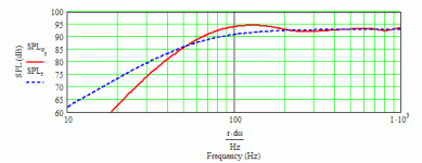
With the above specs, 45" long, going from 8"x8" tapering down to 2"x2" and fully stuffed with ~250g of polyfill looks good in simulation. Net volume is ~19L if I use a Conical flare, close to what you'd get with a pyramid-style build, or ~24L if I use a Parabolic flare, what you'd get if you built a "wedge" with two parallel sides, the other two with a linear taper. You'd have to make the open-end 8" x 0.5" in this case.
This is not the same thing as a Nautilus at this point, as the terminus should be closed and the rear-wave internally absorbed.
This is not the same thing as a Nautilus at this point, as the terminus should be closed and the rear-wave internally absorbed.
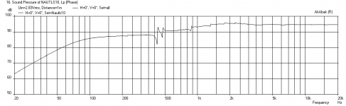
Sim of 60 in long TL with Lcao F6
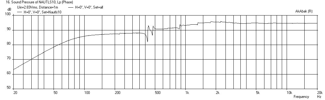
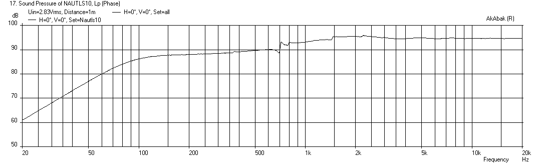
I modeled the 60 in long TL starting with a 8 in x 8 in baffle where driver is mounted tapering to a 8 in x 2 in tail or terminus. It is moderately stuffed with damping material equivalent to a pressure drop of 7500 Pa/m^3. There are two cases with the vent open and closed.
With rear vent open freq response (4 pi open space far from walls or floor) - you can see the effect of baffle step loss:

Note that the vent does not appear to help the bass much and actually causes a cancellation dip.
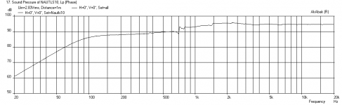
Here it is with rear vent closed (sealed TL):
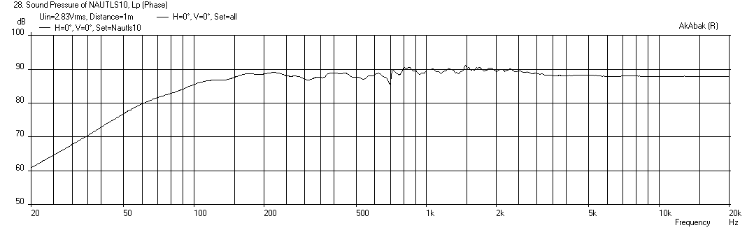
I think you are far better off to make a short (36 in long) sealed tapered TL like the Nautaloss, where the intent is to absorb the rear wave:
If we apply a 1mH & 7.5ohm BSC circuit, here is what we can get:

This response is actually even smoother once real stuffing/damping is applied. If we include the effects of floor bounce (48 in high) and rear wall (60 in back) reflections in a well-damped (absorbcoeff=0.75) room, we get this:
In summary, I don't think you will be very happy with the 60 in long vented speaker. Make it shorter and make it sealed, otherwise design a traditional TQWT box type offset driver TL like a Voigt pipe, etc.
I modeled the 60 in long TL starting with a 8 in x 8 in baffle where driver is mounted tapering to a 8 in x 2 in tail or terminus. It is moderately stuffed with damping material equivalent to a pressure drop of 7500 Pa/m^3. There are two cases with the vent open and closed.
With rear vent open freq response (4 pi open space far from walls or floor) - you can see the effect of baffle step loss:
Note that the vent does not appear to help the bass much and actually causes a cancellation dip.
Here it is with rear vent closed (sealed TL):
I think you are far better off to make a short (36 in long) sealed tapered TL like the Nautaloss, where the intent is to absorb the rear wave:
If we apply a 1mH & 7.5ohm BSC circuit, here is what we can get:
This response is actually even smoother once real stuffing/damping is applied. If we include the effects of floor bounce (48 in high) and rear wall (60 in back) reflections in a well-damped (absorbcoeff=0.75) room, we get this:
In summary, I don't think you will be very happy with the 60 in long vented speaker. Make it shorter and make it sealed, otherwise design a traditional TQWT box type offset driver TL like a Voigt pipe, etc.
Attachments


Last edited:
ig81, xrk971, gm,
I value your helpful advice. thank you! something to clarify my application:
I will use the speaker as full range down to 100hz. I do not need lower as i have very good stereo subs that play clean into lower mids.
if there is a TL box that is optimized, this would be the time to make the best of 100hz up rather than a wider bandwidth with a "dip" in the midbass. good midbass is very valueble to me and i have a good solution for below 100hz already (four 12" in sealed boxes).
any suggestions for constructing a true tapered tube? fiberglass?
regards.
The design I provided you above with 36 in long taper going from 8x8 in to 8x2 in sealed end basically satisfies your request for 100 Hz extension (circa -3dB at 100 Hz). That is about as flat of a response as you are going to get from this driver in any alignment. Just be sure to use a BSC circuit for balanced sound. It should integrate very well with a sub XO at 100 Hz.
thank you, xrk971.
what software or app do you recommend for modelling this project? i want to see what you see! although i do believe you.
regards.
what software or app do you recommend for modelling this project? i want to see what you see! although i do believe you.
regards.
thank you, xrk971.
what software or app do you recommend for modelling this project? i want to see what you see! although i do believe you.
regards.
Noviygera,
You are welcome. You can model this with several different software packages. Hornresp is probably the easiest and most user friendly - and David McBean is very helpful and responsive in the Hornresp thread (in subwoofer forum). I use AkAbak which is very powerful and flexible in that it can model just about anything only limited by your imagination. However it has a steep learning curve. There is also the MJK worksheets in Mathcad that are also very powerful. If you are interested in the AkAbak route you should check out the AkAbak for dummies thread over in AVS forums. I can provide the script for this speaker if you want to give it a try.
Regards,
X
I value your helpful advice. thank you! something to clarify my application:
You’re welcome!
~2.629 ft^3 net Vb/~111 Hz Fp TL that may not need any baffle step compensation [BSC] and/or allow a lower 70-80 Hz XO point:
L = 27.125”
CSA [WxD] = 167.49”^2
Zdriver = 5.7”
All dimensions inside [i.d.] and approximate. Sim assumes a 1.75 lb/ft^3 stuffing density of polyfil, but most folks normally wind up with much less than suggested when tuned by ear and the driver is used wide range, i.e. will have a bit less flat, but more ‘lively’/life-like presentation, yet be better damped than BR or even some MLTL or TQWT alignments.
GM
Attachments
Faital 6FE100.
The upside to that low Cms is high excursion-limited power handling.
I don't see how Fs could be lower if I measured at higher excursion since the suspension only gets stiffer and things would start to be non-linear anyway.
Not sure I'll ever drive them hard enough in everyday use to loosen it up too.
True.
True, at least until it loosens up.
Good point and why me n’ others have been known to alter/damage the spider’s compliance as required. A few well placed cuts or ‘boiling’ [not literally!] the starch out of them can do wonders. The latter usually takes more heat than a hair dryer though, so only for those that already have a fairly expensive high temp commercial version. The downside of course is the potential to turn them into paper weights…….
In your case, maybe mass load them, lowering Fs/raising Qt, then using the TL to compression load them like the B0$3 WC.
GM
I gotta say Qt>~0.7 is bugging me more than the higher Fs. I may give them some more time to loosen-up. In the meantime, 15L sealed and well-stuffed should not be too horrible as a quick and simple temp build.
GM,
It's a 48" long ~40L ML-Voigt (expanding pipe) with driver tap ~42% (20") and a ton of stuffing in the whole length.
I have no practical experience with such a combo though, can only sim and guess how it'd turn out.[/QUOTE]
FWIW, I used my decades old vented pipe horn ‘subs’ [AKA ML-Voigt, ML-TQWT, ML-horn depending on who is using them] to vet MJK’s original WSs and they were close enough for me [no damping].
After Celotex went the way of the Dodo bird, all my damping has been done with acoustic fiberglass insulation used mostly as a lining, so my crude 1/3 octave ‘as built’ measurements are enough different to probably be audible if they weren’t XO’d at 120 Hz/2nd order. Over this narrow a BW, the room dominates, so I mainly only concern myself with ensuring there’s no audible ‘ringing’, i.e. a critically damped alignment [‘tight’/heart attack ‘fast’ transient response].
GM
- Status
- Not open for further replies.
- Home
- Loudspeakers
- Full Range
- tapered tube FR enclosure (Nautilus)