Hi all,
Today I made a program which graphs the total resistance across a potentiometer when you add tapering resistors to get various behaviors. Its probably common to say, taper a 250k pot down to a 100k pot and so forth. But you can do things like start at 10k, peak, then go down to 5k as you turn the pot, or make then antilog taper go at different rates. I basically made this for me and thought I might as well put it up because I wasn't able to find a grapher like this.
https://sites.google.com/site/garydavenportelectronics/java
Please give any comments or suggestions.
Thanks, Gary
Attachments
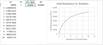
If you go to the website/link above, you'll see a spreadsheet with R1,R2, R3=Rpot, and R4. You can enter values and the graph will automatically update as you change their values. and show you the total resistance of the pot from lug to lug as the pot is turned from 0 to 10. You can download it also, but it has to be opened in a spreadsheet program like excel or openoffice/wpsoffice which are free.
don't worry about changing the values on the website, they automatically go to defaults when you refresh the screen or leave and come back.
Its similar to Joe Davisson's calculator, Analog Alchemy - EMH
but this shows the behavior as you turn the pot from 0 to 10 as it is not linear.
I think its useful in a few ways. Say you need a 100k pot but only have a 250k pot, you can use this to get a 100k pot substitute. In a circuit I have, I needed a pot to go from 33k to 100k with 68k in the middle. I know you can add in series, but this way, I pull out the existing pot and stick this in where the old pot is. Sometimes its nice not to have a resistor hanging of the side of the pot also if you're doing surface mounted soldering too.
The secret life of pots by RG Keen
The Secret Life of Pots
has a great discussion, but this graphing ability I think is very helpful.
I stumbled accross the folowing edition of "Audio".
See page 19 and further...
http://www.americanradiohistory.com/Archive-Audio/60s/Audio-1965-02.pdf
See page 19 and further...
http://www.americanradiohistory.com/Archive-Audio/60s/Audio-1965-02.pdf
Yeah, the OP doesn't understand pots are generally used for attenuation 😉 The results looked wrong so I did my own spreadsheet and found his calculates resistance across the pot, not terribly useful unless you just want a variable resistor....
Thank you for the article
Thank you Tarzan for the wonderful article. I'm downloading it to keep. I have seen that before, and it would be nice to have a grapher for that also. I'm surprised there isn't an online grapher for that application because as Ron E has mentioned that is a much more common use. That is a 3 node nonlinear voltage divider basically and its commonly used to convert a linear pot to an audio taper but can be used in different ways. There is a "Vin" node, "a ground", and a "Vout" node.
The graph I made was for a 2 node model, not 3. This way a 2 node variable resistor can be inserted into a circuit, replacing a fixed resistor wherever you might need one. I was using it in just this fashion modifying an existing band pass filter in a circuit. Its a little easier sometimes to solder the resistors to the potentiometer and then hook up to the pcb board if your're making a modification to an existing circuit.
"The way its drawn and calculated you hook up to the outer lugs of the potentiometer"
- Status
- Not open for further replies.
- Home
- Design & Build
- Software Tools
- Tapered Potentiometer Grapher